This experience was pivotal in shaping my career path, as it was where I first learned to use Fusion 360 for 3D design and manufacturing custom components through CNC machining and 3D printing. Competing at FRC events allowed me to showcase these technical skills while engaging with sponsors who offered internships in design and rendering, recognizing the real-world applicability of what I had mastered. Beyond technical expertise, collaborating with a large team to build industrial-scale robots and presenting to judges honed my communication and leadership abilities, preparing me for a career in robotics, automation, and innovative technology development.
FRC 2023 Season
Co-lead of 3D Design & Build on Team 4069 Lo-Ellen Robotics
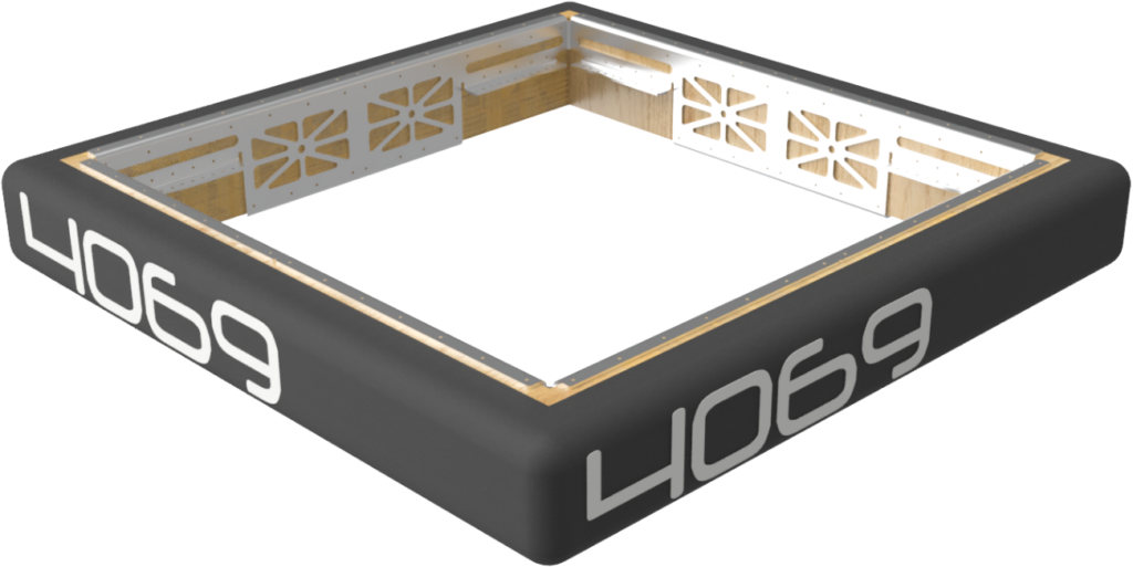
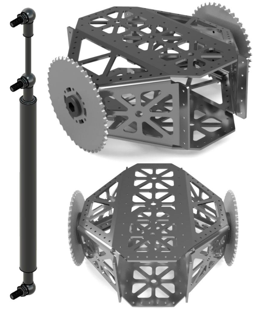
Swerve Drivebase
The drive base allows the robot to maneuver around the field quickly and precisely. Unlike the past nine years of tank drive, this year features Team 4069’s first-ever swerve drive base. Our team decided to use swerve drive to achieve fast cycle times while maintaining a small and agile drive base.
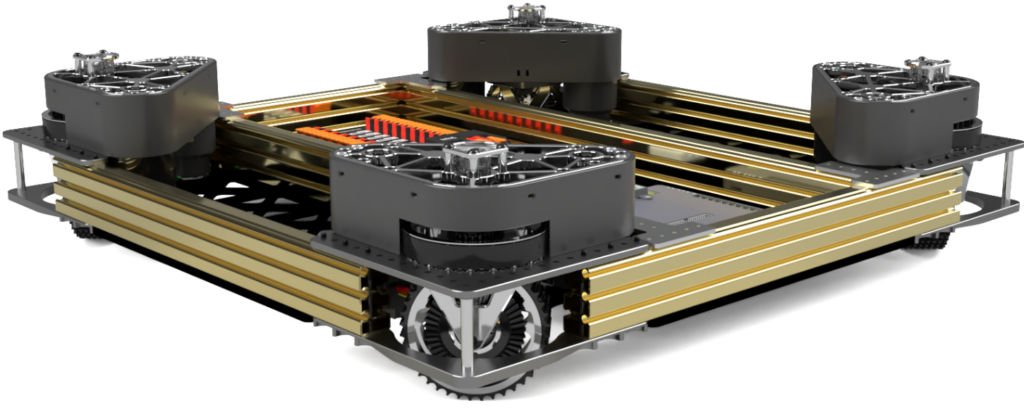
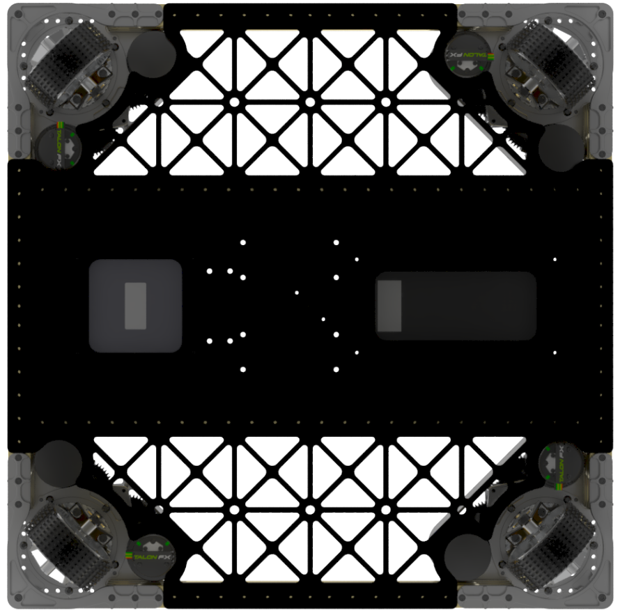
Having a small robot frame perimeter of only 26” square was crucial in order to have an agile robot. Consequently allowing three robots to fit comfortably on the charge station while balancing.
We originally made the frame out of 2’’ x 1” extrusion to hold together the swerve modules. However, as it was too heavy, we switched to aluminum walnut extrusion. Additionally, we changed the drive base from 24 x 24” to 26 x 26” to increase the overall stability.
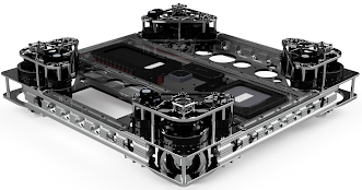
We mounted the gyro directly in the centre of the robot for the most accurate point of reference for our center of rotation.
Our chosen Swerve modules were the SDS MK4i’s, as they were very versatile with the given mounting holes and the different options for drive gear ratios. As this was our team’s first year using swerve drive, we spent the offseason testing different gear and motor options, starting with L1 gears and quickly moving to the faster L2 gearing. This provided the needed speed for our robot, but we quickly realized that this wouldn’t give us enough of the required torque. When the game was released, we rebuilt the modules using Falcon 500s as the driving motors to provide us with even more speed and, more importantly, more torque.
Bumpers
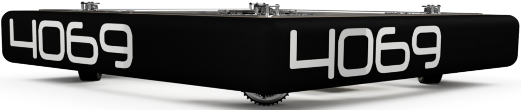
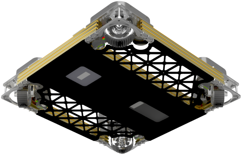
Custom brackets were designed to mount the bumpers securely to the robot base and incorporate a counterweight to lower the robot’s centre of gravity, improving traction and stability while driving and placing game elements. The heavier and stronger bumper brackets enclose the fabric and the wood to withstand sufficient impact and the rigours of the match. Hand screw coupling nuts allow the bumpers to be securely mounted while allowing quick removal for maintenance and alliance changes.
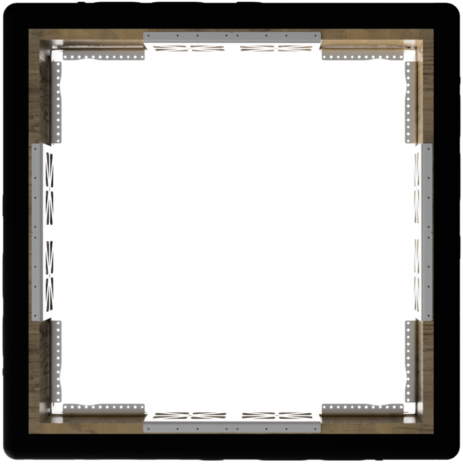
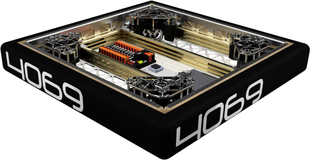
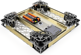
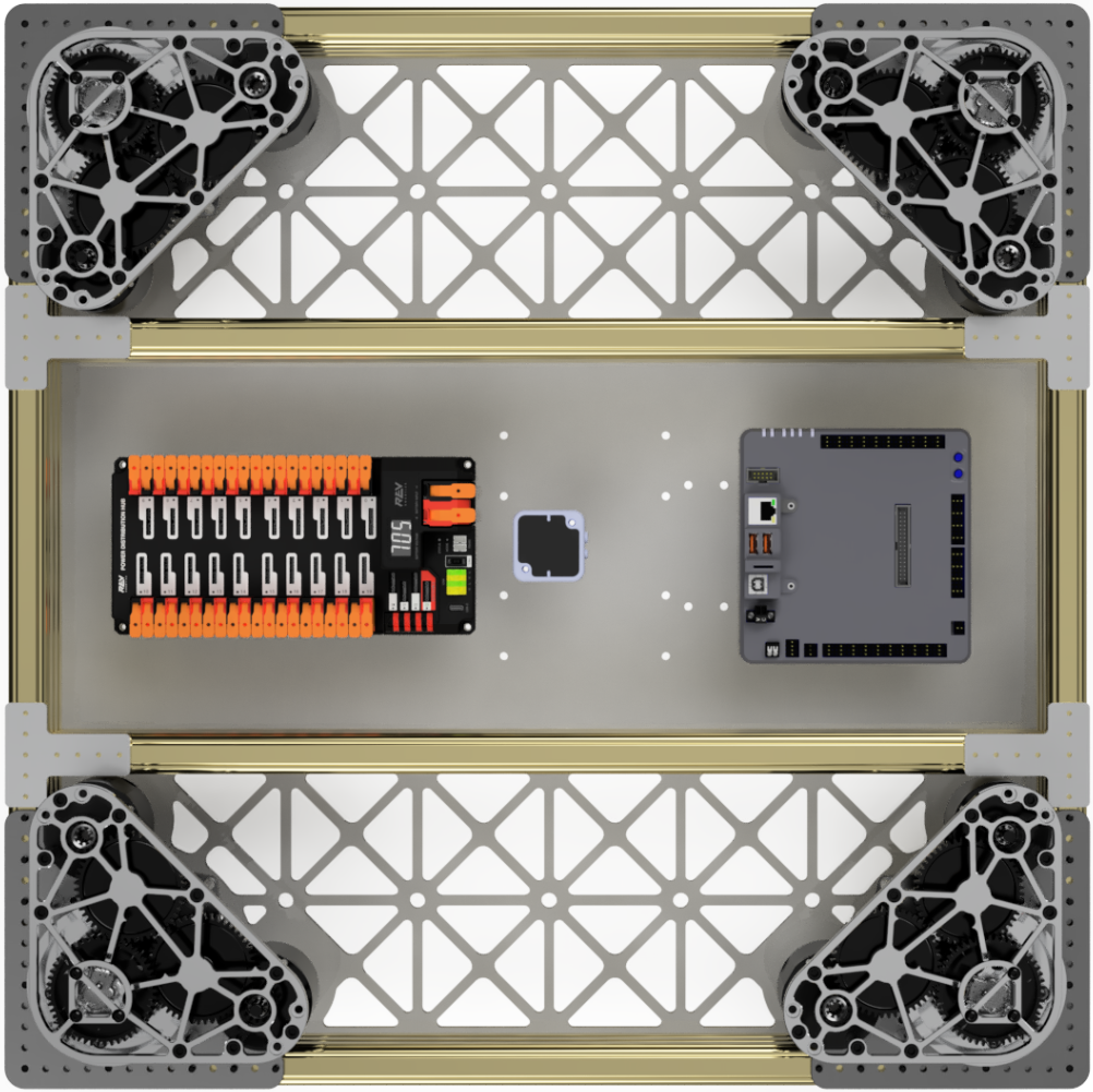
Electrical
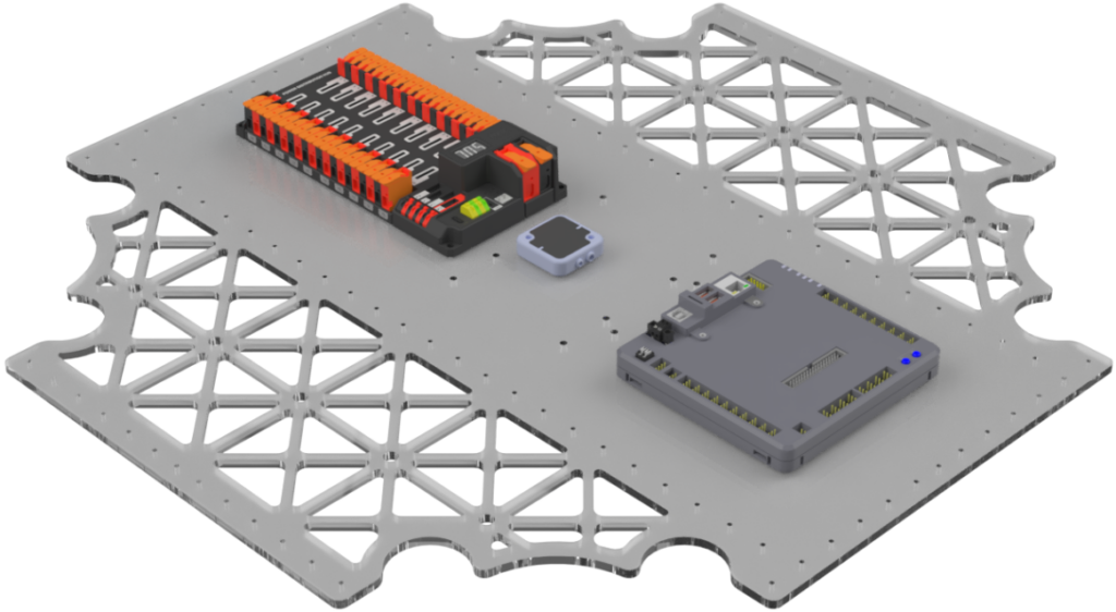
The electrical panel is incorporated into our belly pan, which was purposely placed low on the robot to lower the centre of gravity and create a strong base for the electrical components to be mounted. The belly pan adds angular rigidity when encountering impacts from defending robots and game elements.
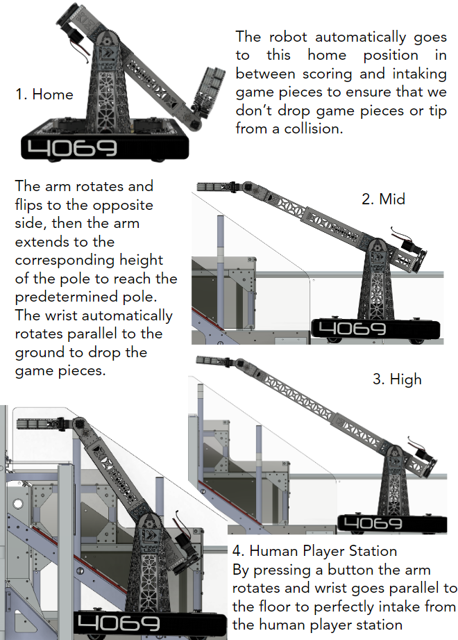
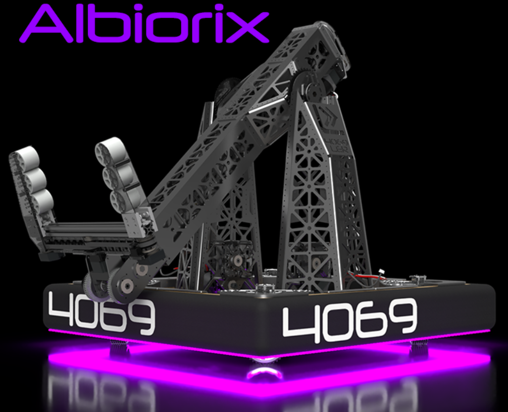
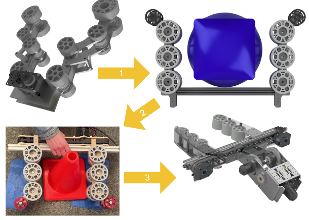
Robot Design
We have 5 different subsystems on the robot.
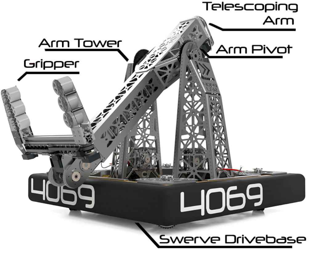
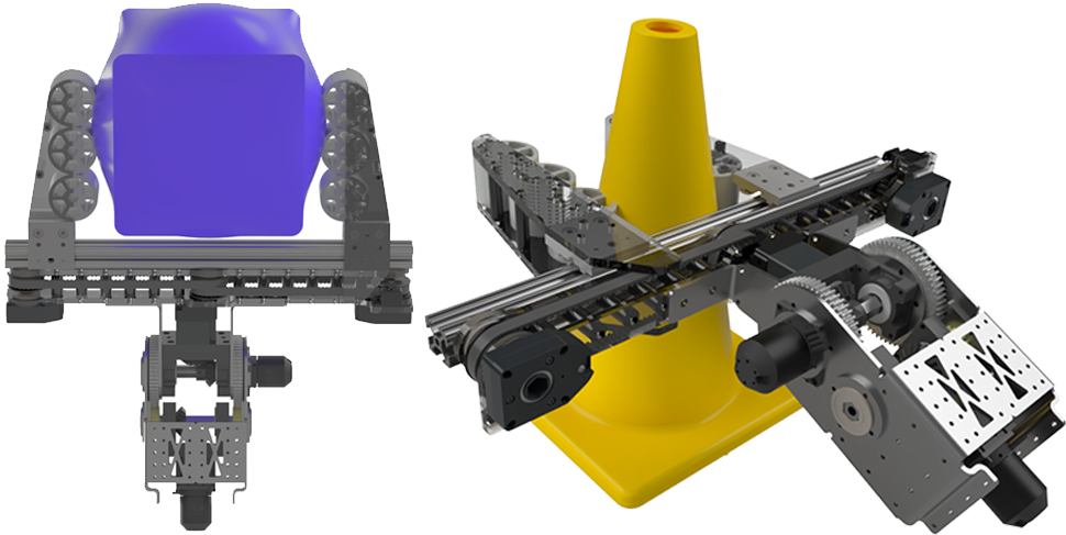
Gripper
We used small 2-inch flex wheels, providing the required amount of grip while being lightweight. We decided on this clamping pincer design rather than a roller intake to save weight as it uses fewer bearings and shafts and simplifies the design by using fewer moving parts. Mounting 2” flex wheels in an offset position gave us more compliance than the 3” flex wheels we had on our original prototype.
We used small 2-inch flex wheels, providing the required amount of grip while being lightweight. We decided on this clamping pincer design rather than a roller intake to save weight as it uses fewer bearings and shafts and simplifies the design by using fewer moving parts. Mounting 2” flex wheels in an offset position gave us more compliance than the 3” flex wheels we had on our original prototype.
After our first competition, we changed our intake design. We had difficulty gripping cubes by closing both of our grippers simultaneously, as the cube had to be perfectly centred in the claw. Therefore, we added 2 sets of 2″ flex wheels driven by a NEO 550 on either side to intake the cube passively, and then the grippers would close to hold it. This allowed us to have more room for error when intaking a cube and quicker cycle times.
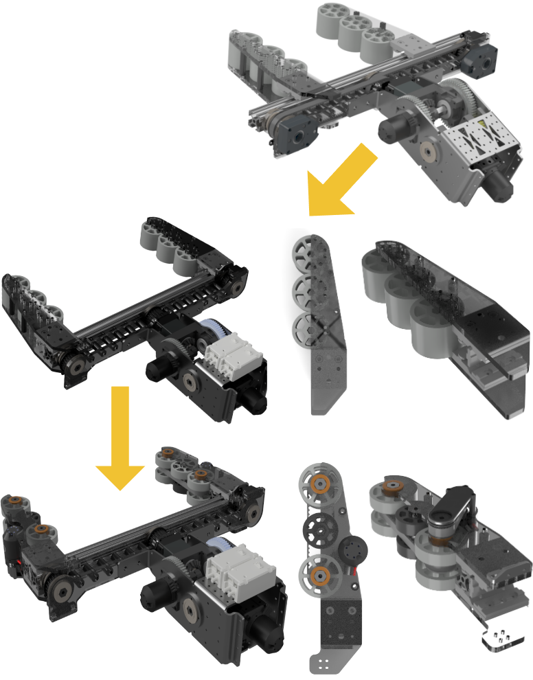
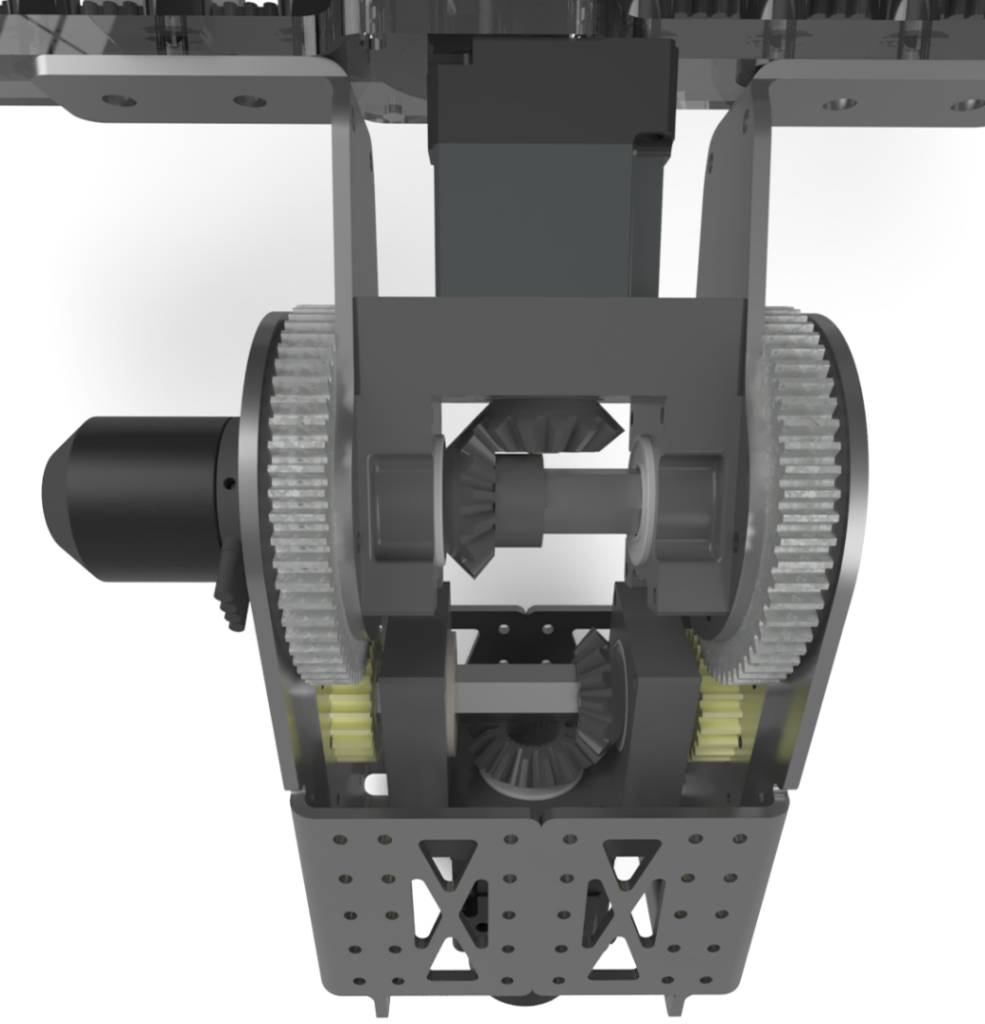
Wrist

The original design did not use bevel gears. Students custom-machined and designed dual 90-degree gearboxes, which are more compact and reduce the weight at the end of the arm. Having the motors and gears inside the arm reduces the risk of damage during competition and simplifies the design.
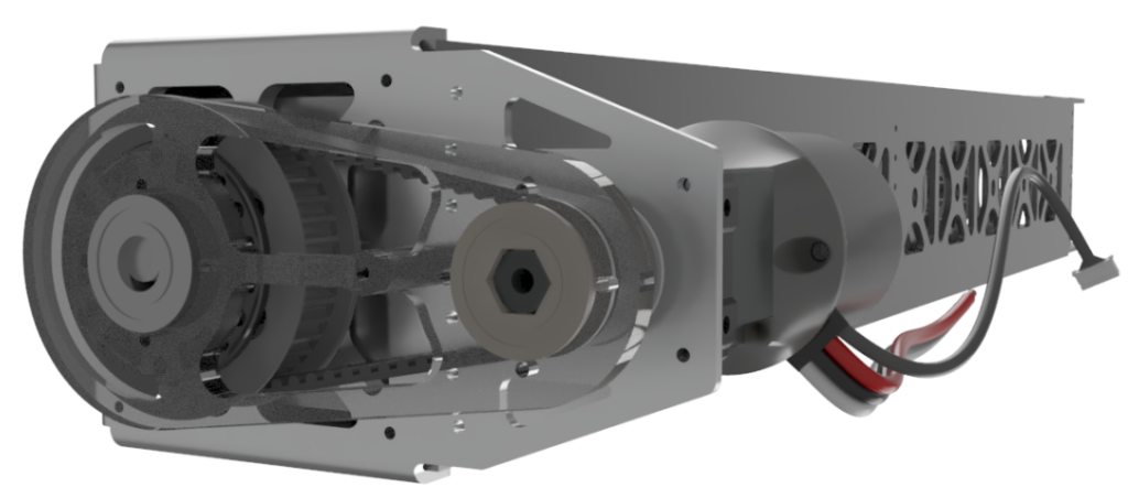
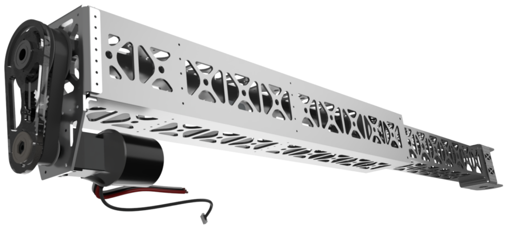
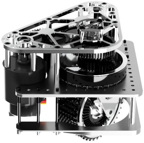
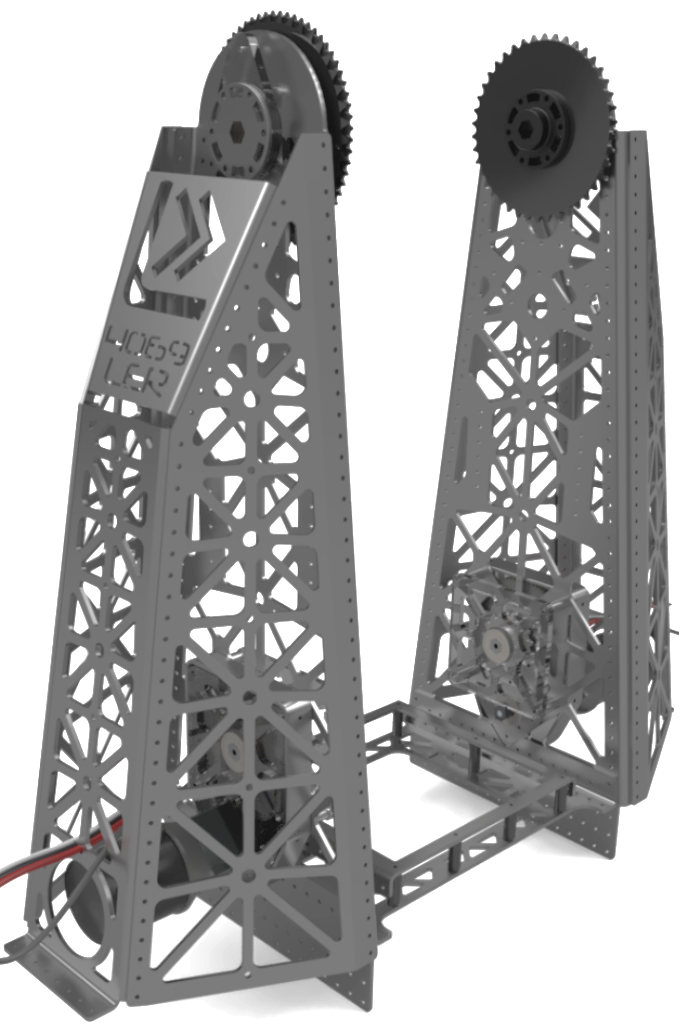
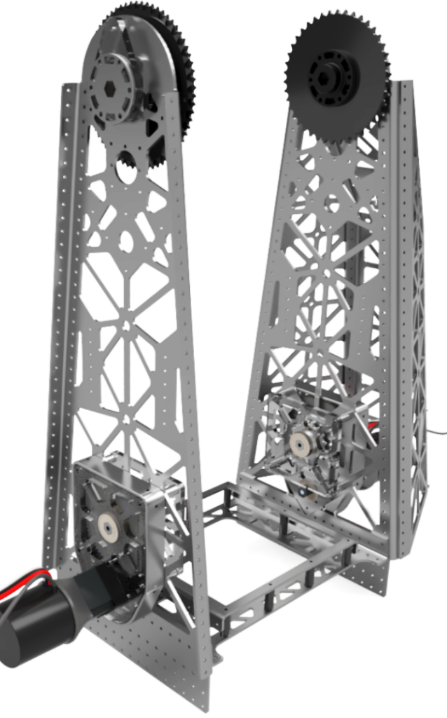
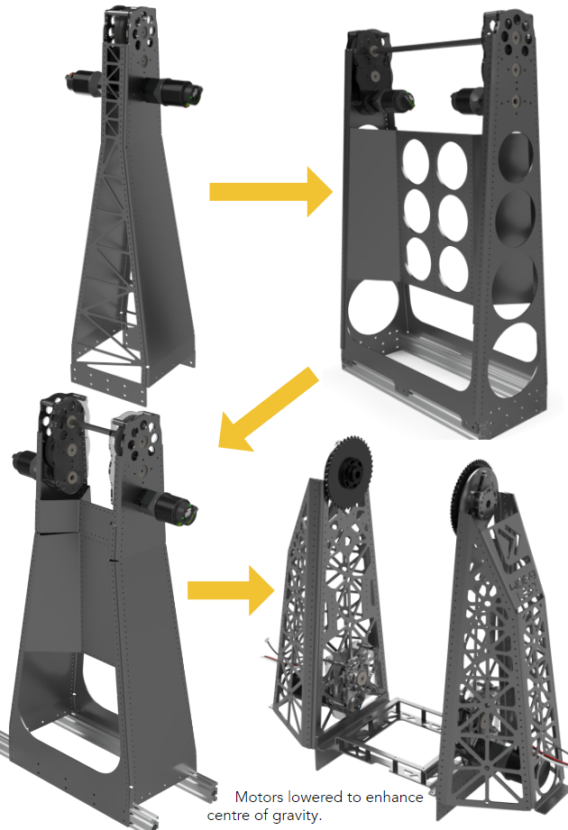
Arm Tower
As students, we designed fully custom gearboxes based on our 2022 climber gearbox, where the bulletproof design was proven, with no repairs or maintenance having to occur throughout a season of climbing. Powered by a NEO motor geared to 20:1 and externally geared with 24:78 gears and a 15:42 sprocket gives an overall ratio of 182:1
Design Process
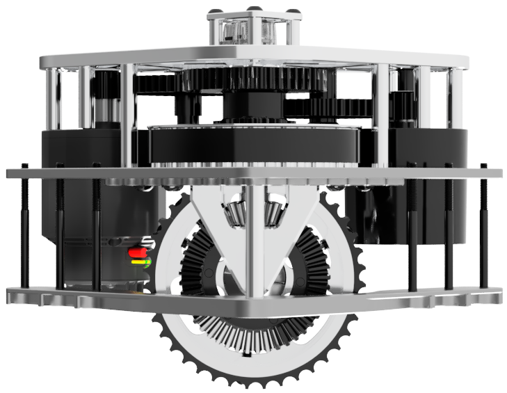
Arm Pivot
We used two gas springs on either side of the pivot to reduce the amount of strain on the motors from the weight of the arm due to the presence of gravity. We employed an octagonal design to triangulate the arm at the pivot point, which distributes the force on the arm while experiencing side loading. #35 chain sprockets are rigidly mounted to the pivot point to reduce the amount of arm backlash usually found in high-load-driven hex shafts.
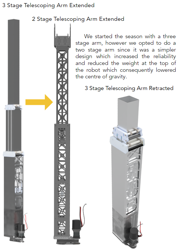
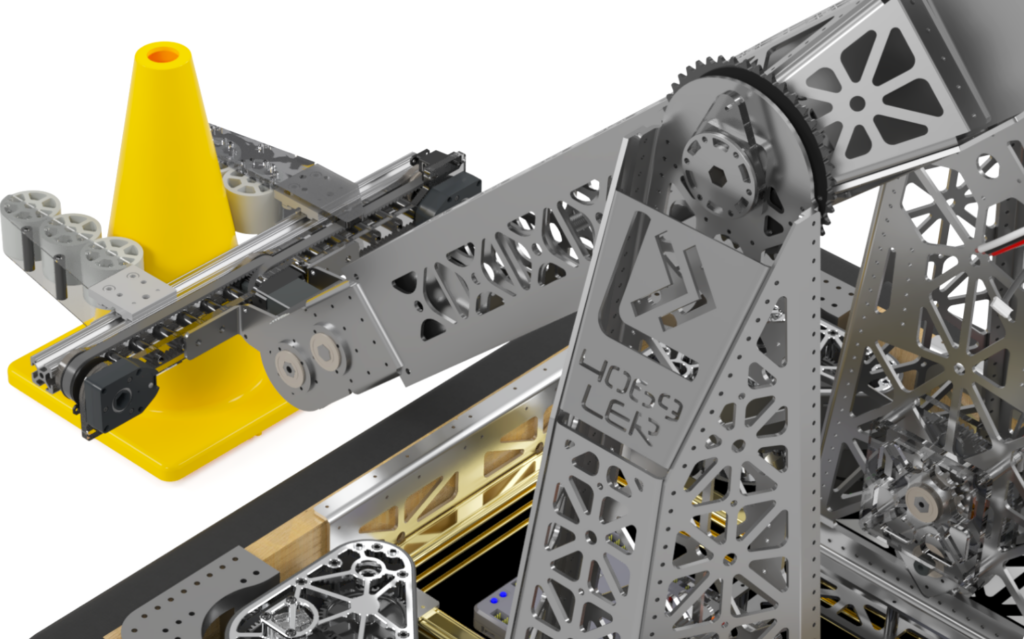
Telescoping Arm
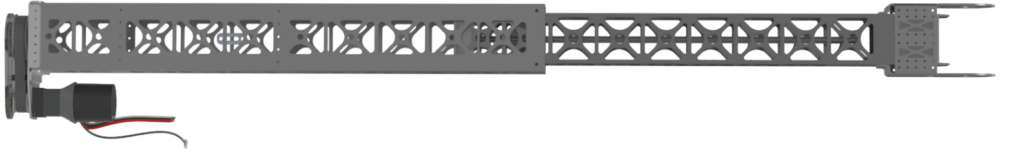
Due to our frugality, we could not afford to waterjet cut our Box tubing for the pocketing. We endeavoured to use a hand router to make each hole by following a wooden pattern. Over hours of rigorous labour, we sufficiently reduced the weight of the arm. A lead screw was used instead of a chain or belt to increase the reliability and precision of the extension. Roller bearings were used rather than Teflon slides to reduce friction when extending and retracting the arm.