Excitement always runs down my spine as I’m faced with my opponents when competing with my school in the FIRST Tech Challenge each year of high school. Since freshman year, I have led the 3D design of an 18-inch robot tasked to compete in field games against other teams. As we entered robotics competitions, I envied the people across from us, knowing they had access to a network of professional engineers, multiple practice fields, and sophisticated manufacturing facilities. My team’s location in the secluded north of Ontario and our frugality forced us to get creative to generate novel, cost-effective design solutions. It was my responsibility to design and acquire each piece, but rather than purchasing parts, it meant creating them myself by operating unfamiliar machines and recycling parts from last year. After completing the 3D model of the robot, I create the instructions and manually operate a milling machine to cut our custom aluminum plates, whereas most teams have professional engineers do it for them. This gave me the practical experience that most other students don’t get.
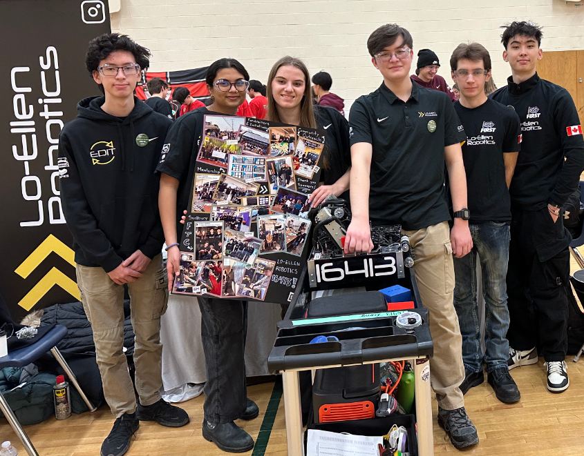
After winning many competitions, I wanted to help and inspire others to show them the same perspective, that your origin doesn’t define the end, so I became a mentor. Since my grade 11 year, I have mentored my younger brothers and five sophomores at each step of the engineering design process, from 3D modelling, 3D printing, programming, manufacturing and rendering their designs, fostering an innovative and inclusive environment. This experience directly relates to my career goals by providing practical skills in CAD, machining, and iterative design while fostering leadership and resourcefulness, key attributes for developing novel robotic technologies or automating systems in industries like ABB or Tesla.
5 Years (Sept. 2019 – Present)
FIRST Tech Challenge (FTC)
Mentoring
Since September 2021, I have had the privilege of mentoring the Lo-Ellen Robotics FIRST Tech Challenge team. This group of five high school students relies on my guidance to navigate the complexities of the engineering design process. From mastering CAD, 3D printing, and CNC machining to honing their programming skills, I lead them through each step. Additionally, I emphasize the importance of interpersonal skills, such as presenting ideas cohesively and working as a team, ensuring our ideals and core values cultivate an inclusive and supportive environment. Also, in my role as drive coach, I strategize with our two drivers, guiding them through in-game match strategies that this year helped us secure eight awards and win both our regional events and 2nd at provincials.
What is FTC?
Each year, the FIRST Tech Challenge provides a unique challenge; teams receive a game manual detailing the rules for a new field game. Competing in an alliance format, teams construct a custom robot with dimensions not exceeding 18 inches in any direction to navigate the point-based game. This year’s challenge involved designing a robot capable of strategically placing 2.5-inch plastic octagons onto a slanted backboard and concluding the 2.5-minute match with the robot elevated off the ground. The game is split into a 30-second autonomous period followed by a 2-minute driver-controlled period, testing both the robot’s design and the team’s driving skills.
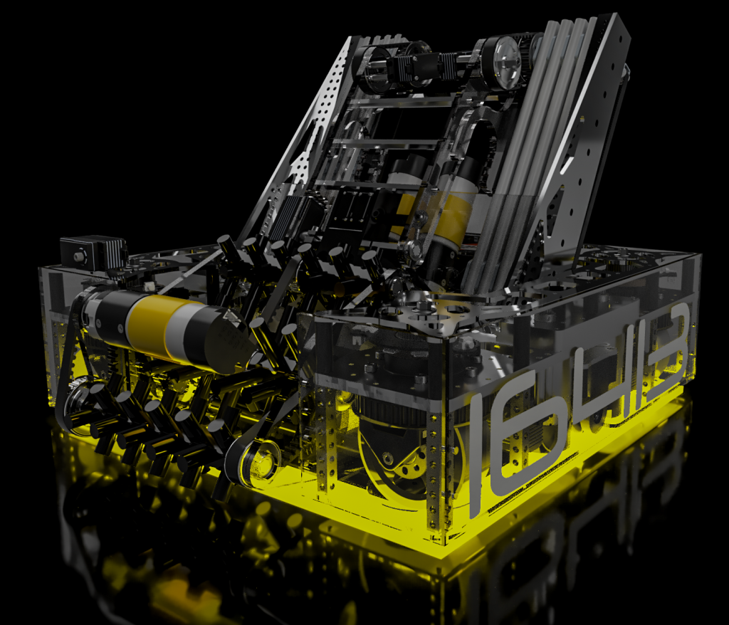
FTC 2025/2024 Season
Mentor of 3D Design, Build & Drive Coach

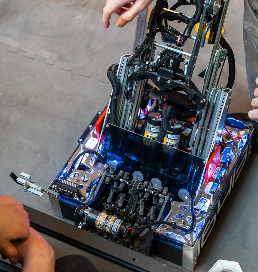
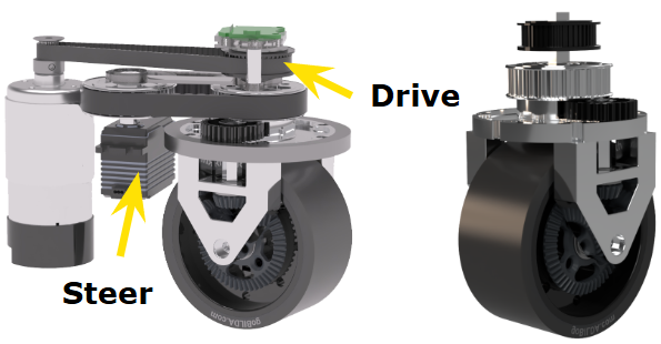
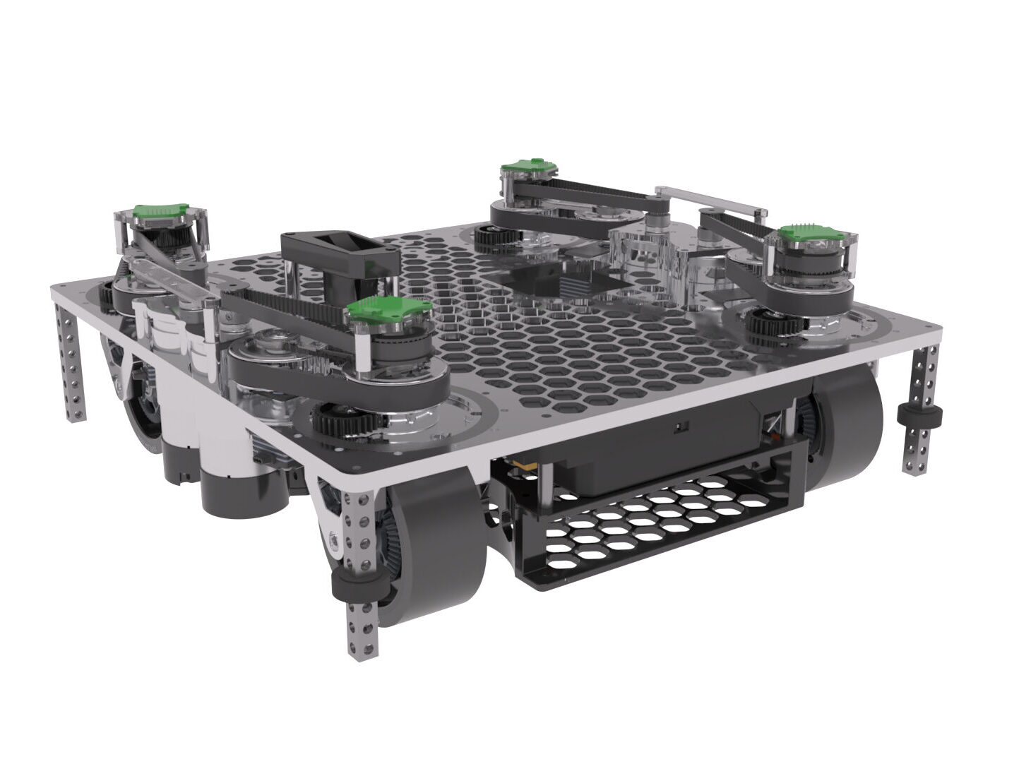
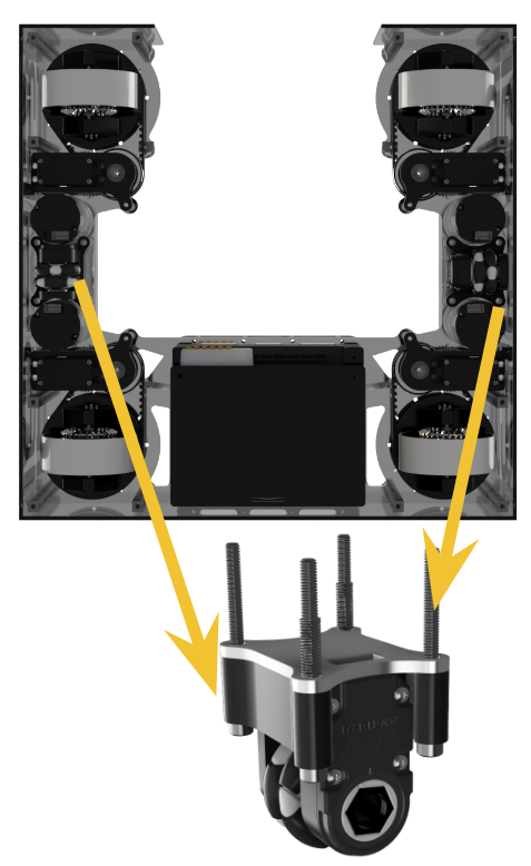
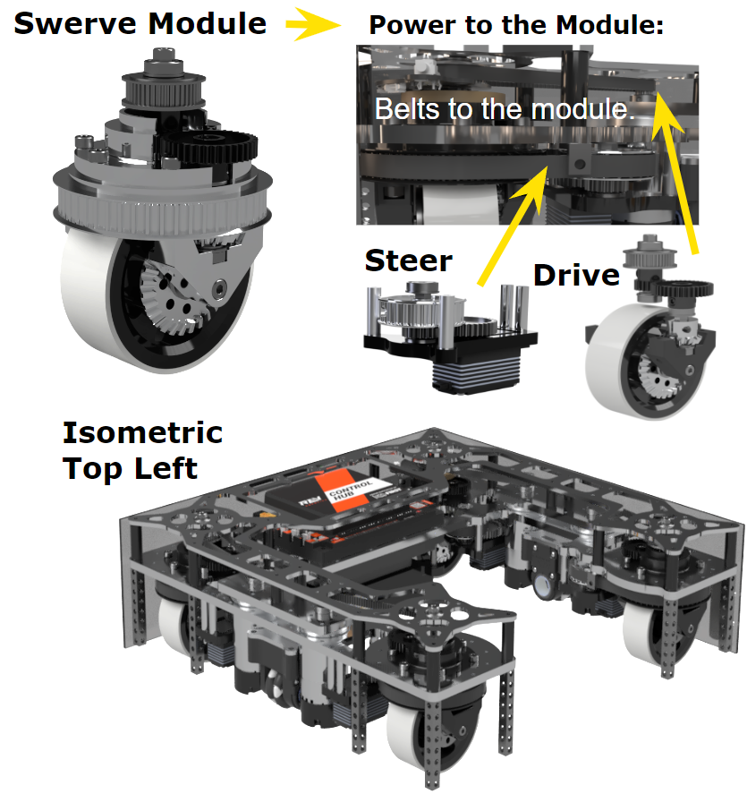
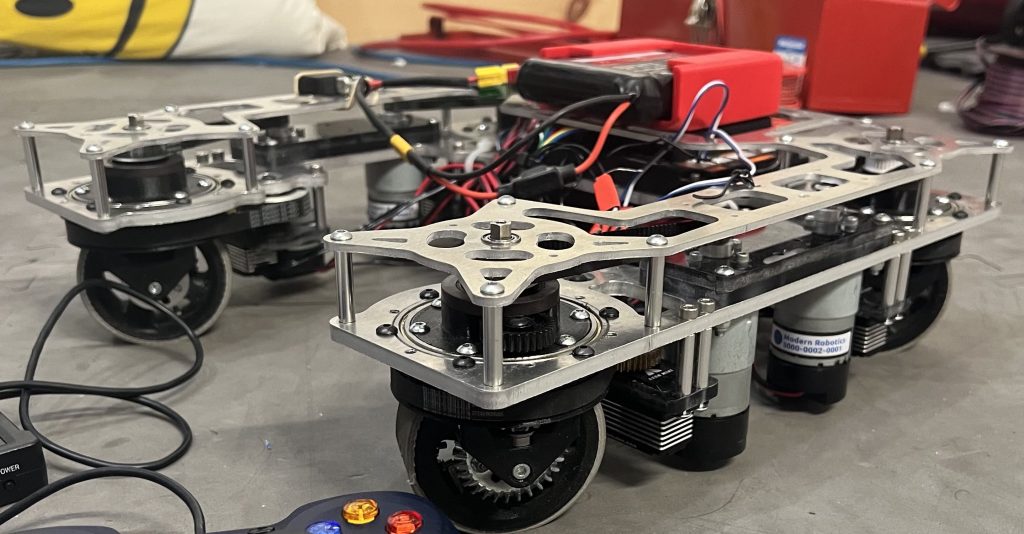
This swerve drivetrain uses four Axon Mini+ servos with a combination of bevel gears and 5mm HTD pulleys to transfer power between the wheels and the 2 types of motors, one that rotates the wheel heading and one that drives the wheel. We chose a swerve drivetrain over a mecanum drivetrain for the design challenge it presents and the superior traction it provides. We decided to make the robot as compact as possible, fitting inside a 12″ by 12″ by 13.5” frame (2” smaller than last year and 4” smaller then the year before). The drivebase’s main structure is made with waterjet ¼ ” 7075-T6 aluminum plates, giving us plenty of rigidity.
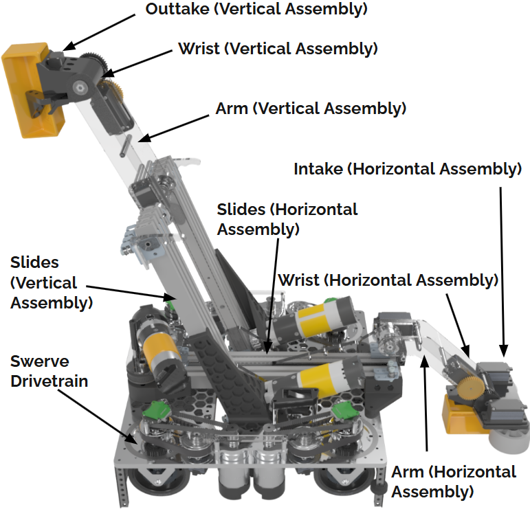
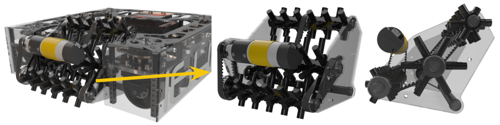
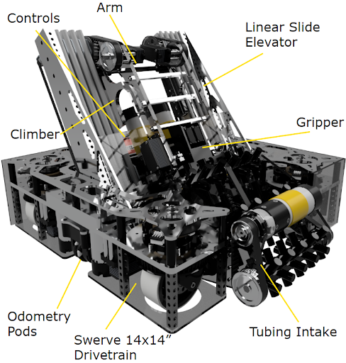
Intake and Horizontal Arm
Our robot features a custom 3D-printed roller intake powered by Axon Minis. The 1:1 gear ratio wrist mechanism relocates the servo for better balance. The polycarbonate arm includes a colour sensor and is just 1/8″ off the floor.
It uses two-stage Misumi slides with a Yellow Jacket motor (3.7:1 ratio) and bevel gears for optimal motor placement, extending up to 22 inches to reach into the submersible.
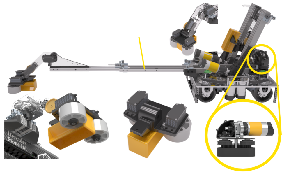
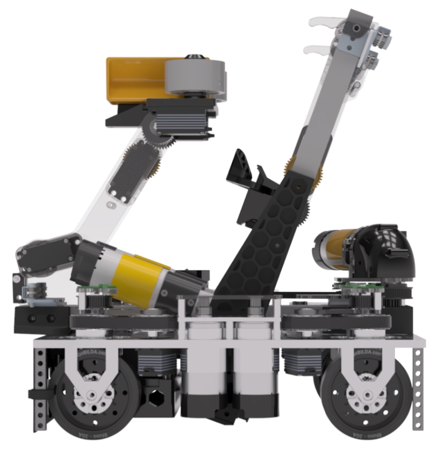
Vertical Claw
Our gripper claw is powered by a single Axon Micro motor in a 1:1 direct drive setup and driven by 2 custom-printed spur gears for synchronized claw movement. It is also designed to fit samples perfectly and ensure smooth horizontal to vertical transfers. Initially tight-fitting, the gripper was adjusted to allow sliding for optimal alignment, with ridges added for enhanced grip and stability.
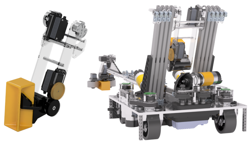
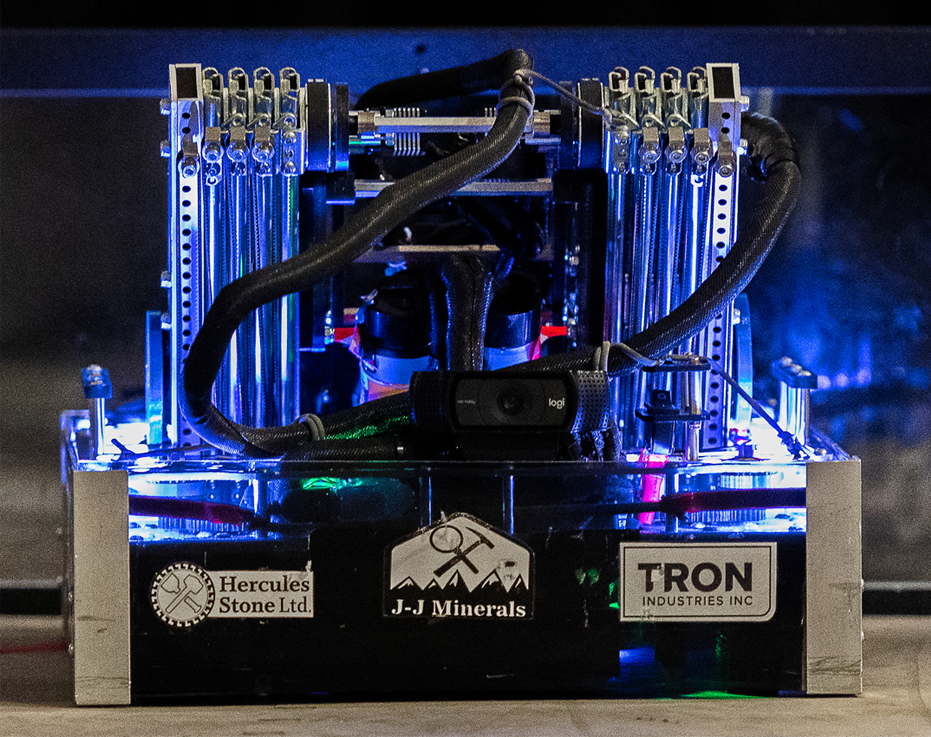
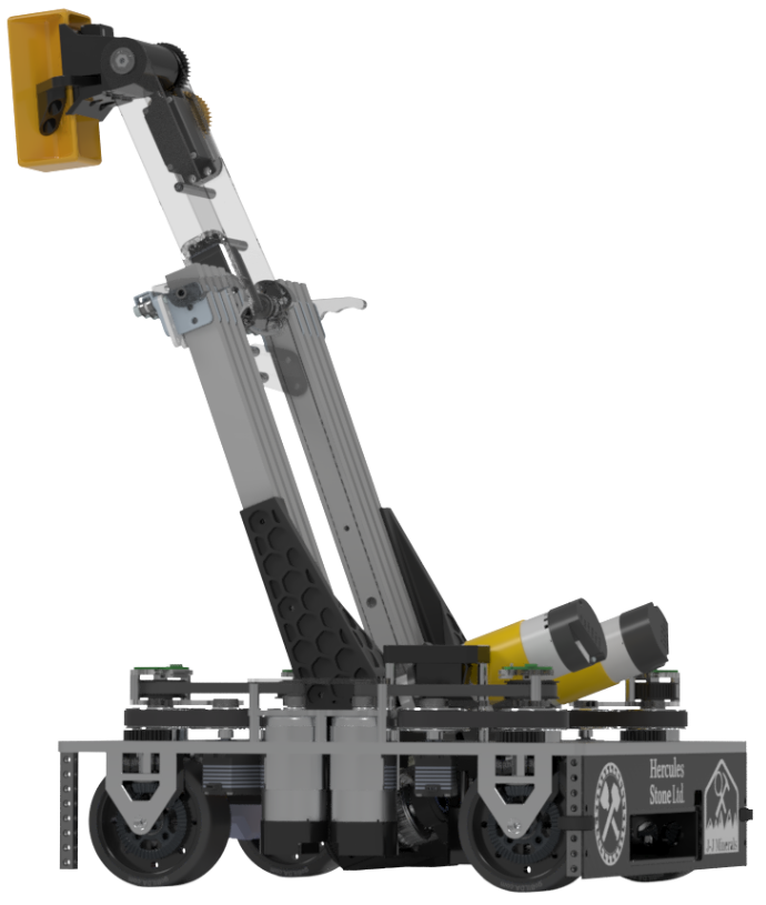
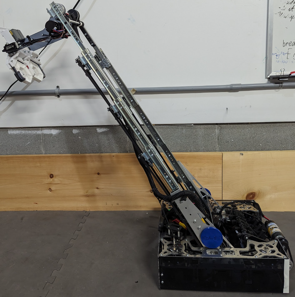
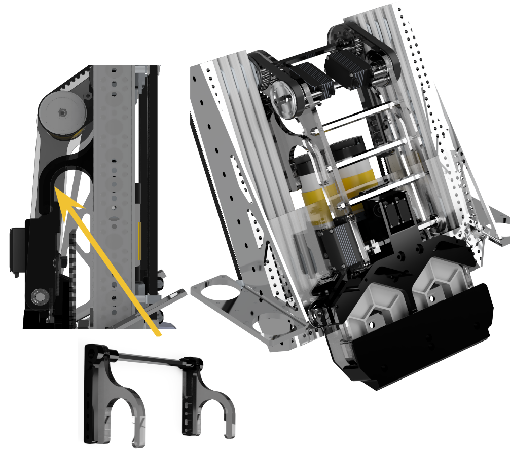
Vertical Slides
Driven by two Yellowjackets (5.2:1) through belts and Misumis, our 4-stage, 20-degree angled custom mount is inset into the drive base for optimal packing and balance. We updated our motor ratio from 13.7:1 to 7.8:1, doubling the cycle speed and enhancing both climbing and cycling efficiency. Initially, the spacing we used between the slides was too close, impacting the effectiveness of the bearing movement. After multiple iterations and size adjustments, we had it tuned perfectly, ensuring the best slide movement.
Climber
Using JVN’s Mechanical Design Calculator, we designed our elevator to lift the robot for climbing, ensuring it could handle the necessary load by testing our battery’s internal resistance. The climber is mounted to the innermost stage at the lowest point. It pulls the bar toward the robot when it retracts, allowing the secondary hooks to latch. After the intermediate latch is secured, the elevator extends again to reach the second bar, completing the climb.
Robot Design
We have 9 different subsystems on the robot.
Drivebase
We originally powered our drivetrain with Modern Robotics motors with an external 11.35:1 ratio. However, this drained too much current from our mechanism, so we changed them to a 12:1 external ratio.
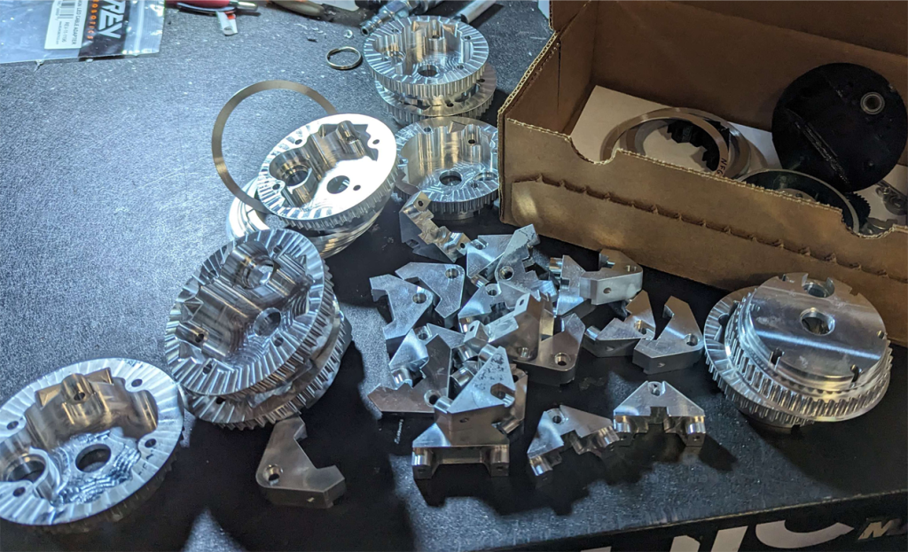
Last year, the robot’s total mass was 32 lbs, but our drivetrain took too much current. To rectify that, we changed to a 12.65:1 ratio, shaving 11 lbs off the robot’s weight to draw 8 amps less current than previously. With the custom billet swerve module, we were also able to make the drivetrain more efficient, reaching a final efficiency of 95% from the motor to the wheel.
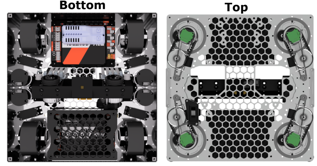
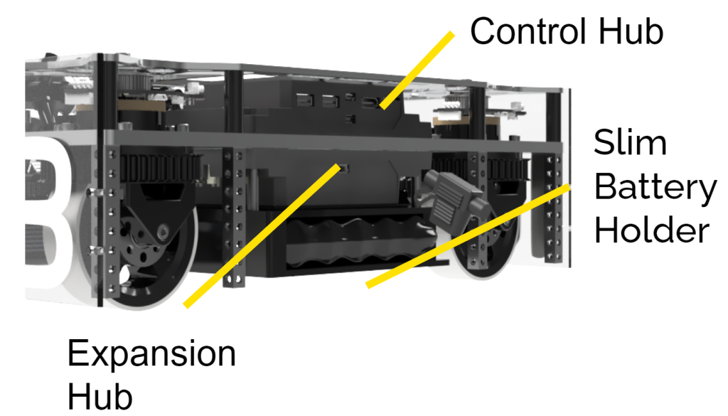
Control Panel
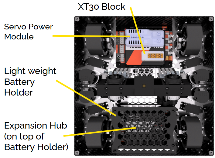
The ¼” drive base panel is cut to fit the Control Hub on the front of the robot and the Expansion Hub on the back, both mounted underneath. Placing the hubs equally on each half of the robot assists in mass distribution. The battery is mounted below the Expansion Hub to lower the robot’s centre of gravity as much as possible to prevent tipping while climbing. Moreover, the specifically selected mounting spot of the battery assists in moving the robot to the correct angle while it climbs to the high bar.
We mounted the XT30 Power Distribution Block and the Servo Power Module underneath the bottom of the robot.
We use the Servo Power Module for the servos that need the most torque (drivetrain + intake wheels) and the 5v Control Hub ports for the lower current applications (arm and wrist).
We have a belly pan underneath our robot to contain the wires on the bottom.
FTC 2024/2023 Season
Mentor of 3D Design, Build & Drive Coach
Our robot’s compact design fits within a 14x14x12-inch frame, which is the smallest we could make it for easily moving around other robots. It is constructed from waterjet aluminum plates for maximum strength and minimal size. We transitioned from Modern Robotics motors with a 6:1 ratio to a 12:1 ratio, improving the current efficiency of our mechanisms.
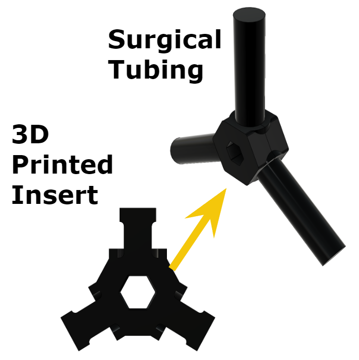
Intake
The intake system consists of surgical tubing on rotating axial and goBILDA wheels powered by a goBILDA motor with a belt reduction system. It pulls the game pieces in and kicks them off the ground into our gripper.
Arm / Elevator / Climber
Our Arm Mechanism is capable of a 250-degree range of motion, seamlessly transporting game pieces from intake to scoring position. Coupled with an Axon Mini+ servo-controlled wrist, the arm features a hard stop for accurate scoring.
We used a 4-stage goBILDA linear slide elevator to surpass the initial scoring line height, enabling quick vertical movement and precise placement of pixels on the scoring backdrop.
The climber utilizes the robust elevator system with polycarbonate hooks to hoist the robot off the ground efficiently, easily meeting the end-game challenge.
Gripper
We designed a dual-sided gripper controlled by two Axon Micro+ servos for optimal control and storage of game pieces, allowing precise placement.
Robot Design
We have 8 different subsystems on the robot.
Drivebase
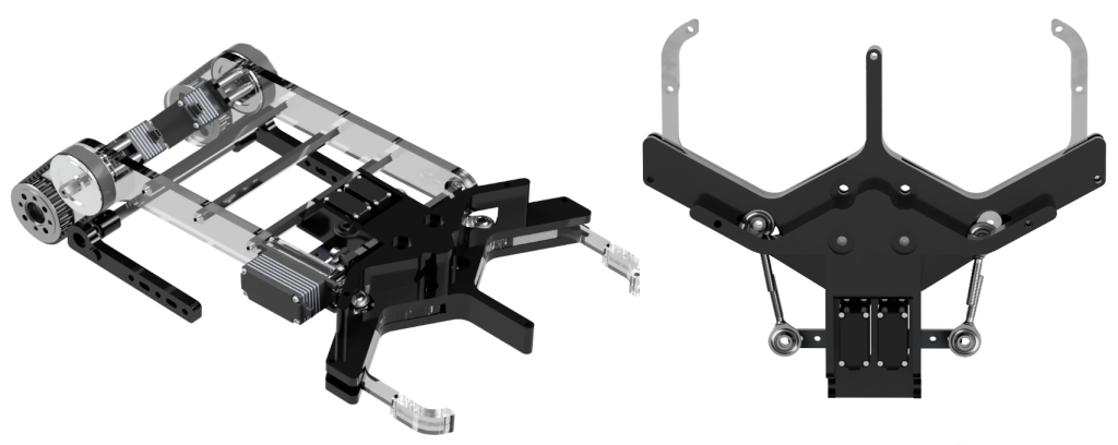
We were the first Canadian team to create a coaxial swerve drivetrain to maximize our robot’s agility and traction, which was critical for the season’s strategic gameplay and required precise placement and robust defence. The sweep drivetrain allows for holonomic movement, meaning the robot can move in any direction without stopping to turn, offering us a competitive edge in maneuvering during matches. The swerve drive uses 4 modules with a wheel on each corner. There are servos for wheel rotation, encoders for orientation feedback, and motors for driving.
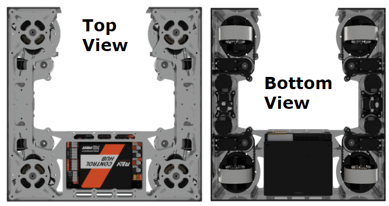
Control Panel / Odometry Pods
We use two small omni wheels with REV encoders, called odometry pods, to determine the robot’s position. One wheel measures movement along the y-axis, and the other along the x-axis. The robot’s heading is tracked using the Control Hub’s built-in IMU.