5 Years (Sept. 2019 – Present)
FIRST Tech Challenge (FTC)

Mentoring
Since September 2021, I have had the privilege of mentoring the Lo-Ellen Robotics FIRST Tech Challenge team. This group of five high school students relies on my guidance to navigate the complexities of the engineering design process. From mastering CAD, 3D printing, and CNC machining to honing their programming skills, I lead them through each step. Additionally, I emphasize the importance of interpersonal skills, such as presenting ideas cohesively and working as a team, ensuring our ideals and core values cultivate an inclusive and supportive environment. Also, in my role as drive coach, I strategize with our two drivers, guiding them through in-game match strategies that this year helped us secure eight awards and win both our regional events and 2nd at provincials.
What is FTC?
Each year, the FIRST Tech Challenge provides a unique challenge; teams receive a game manual detailing the rules for a new field game. Competing in an alliance format, teams construct a custom robot with dimensions not exceeding 18 inches in any direction to navigate the point-based game. This year’s challenge involved designing a robot capable of strategically placing 2.5-inch plastic octagons onto a slanted backboard and concluding the 2.5-minute match with the robot elevated off the ground. The game is split into a 30-second autonomous period followed by a 2-minute driver-controlled period, testing both the robot’s design and the team’s driving skills.
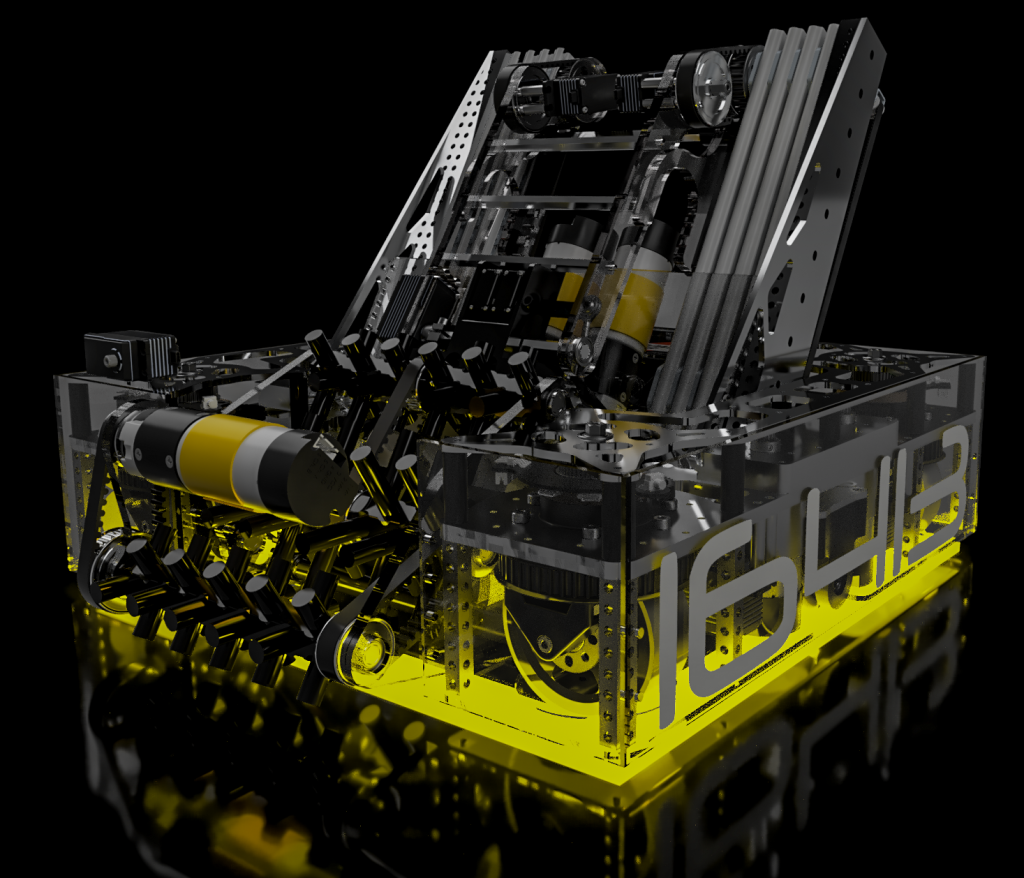
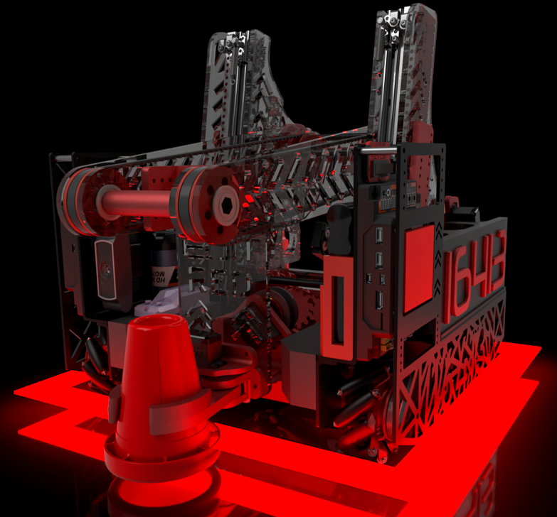
FTC 2025/2024 Season
Mentor of 3D Design, Build & Drive Coach

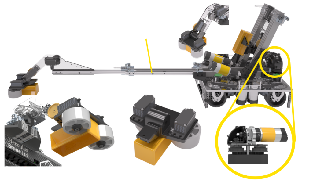
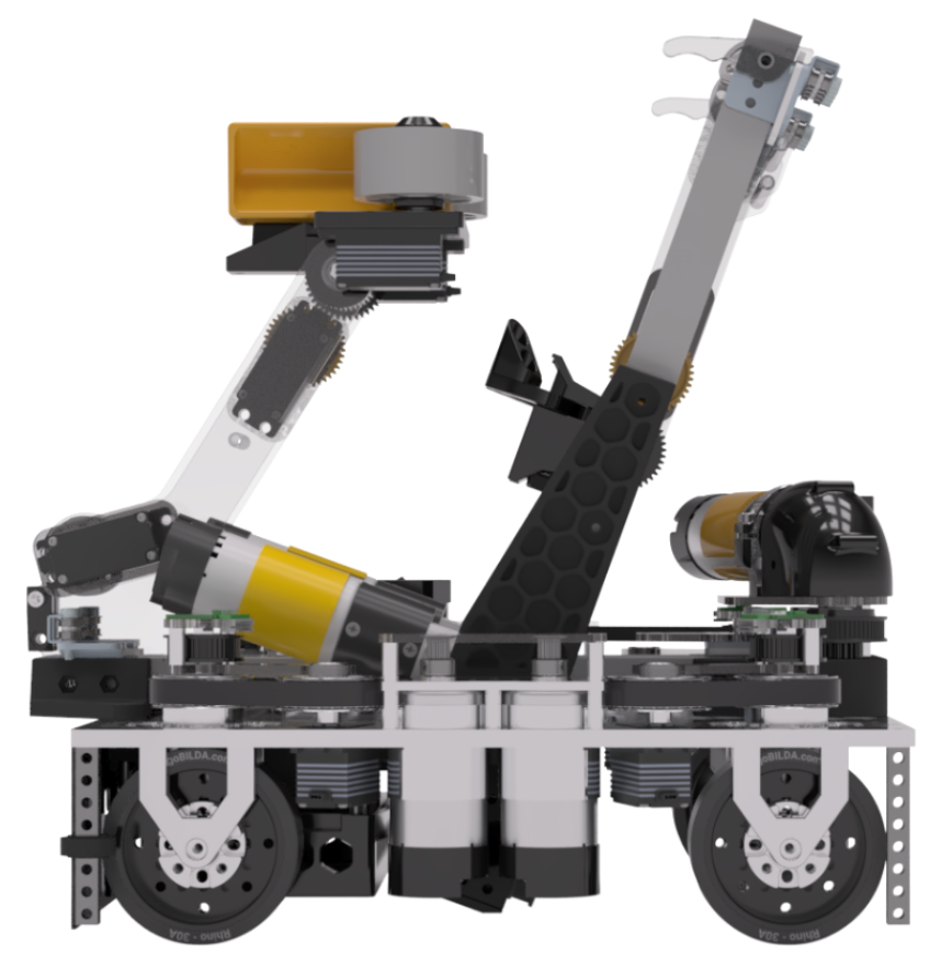
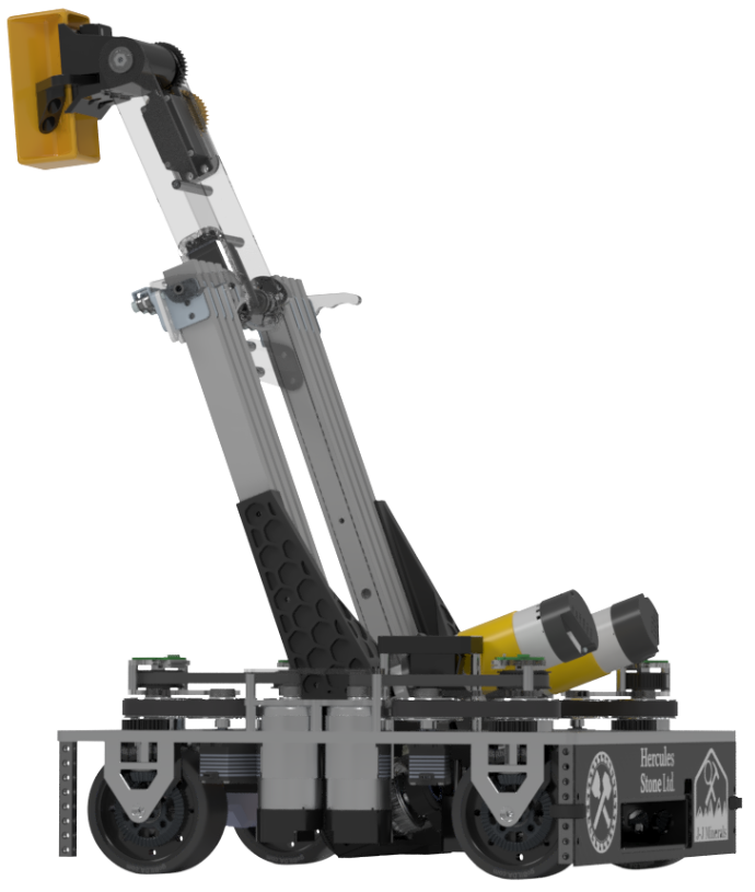
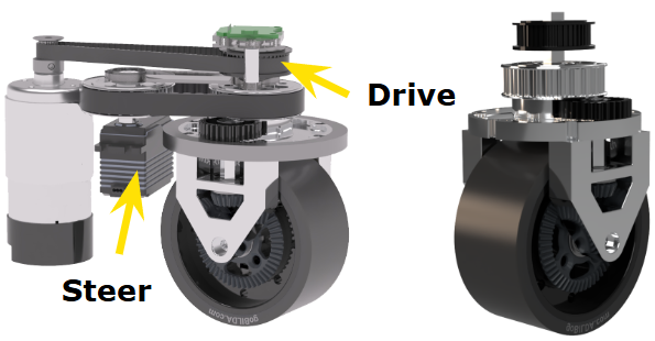
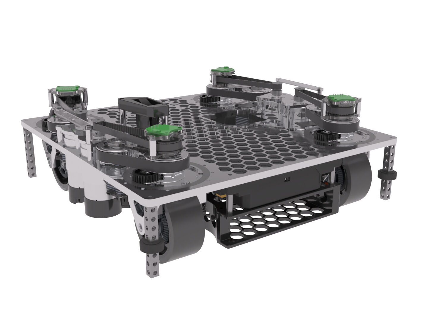
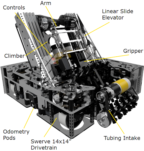
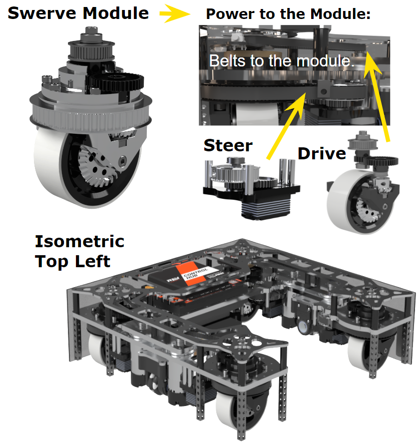
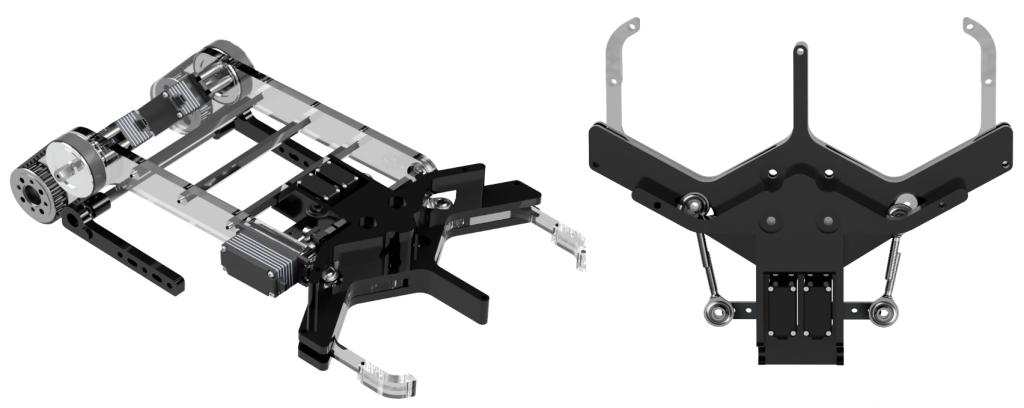
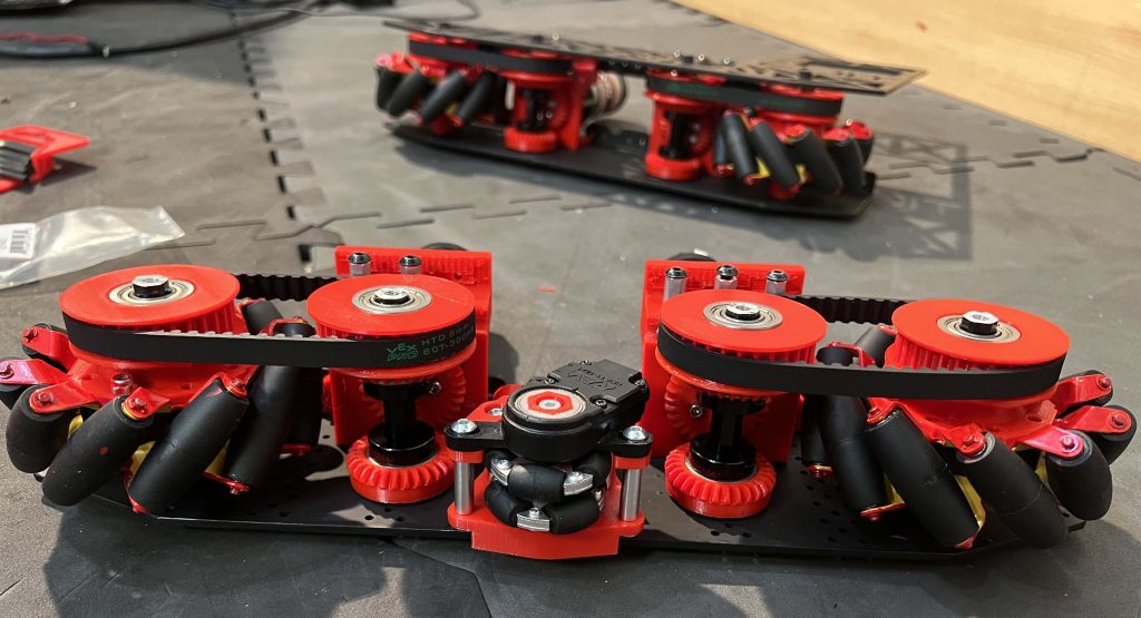
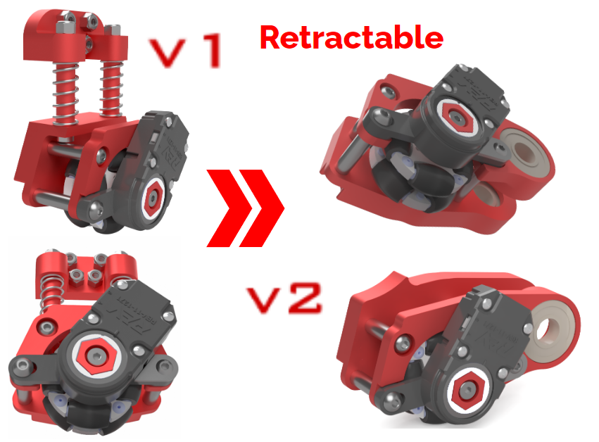
This swerve drivetrain uses four Axon Mini+ servos with a combination of bevel gears and 5mm HTD pulleys to transfer power between the wheels and the 2 types of motors, one that rotates the wheel heading and one that drives the wheel. We chose a swerve drivetrain over a mecanum drivetrain for the design challenge it presents and the superior traction it provides. We decided to make the robot as compact as possible, fitting inside a 12″ by 12″ by 13.5” frame (2” smaller than last year and 4” smaller then the year before). The drivebase’s main structure is made with waterjet ¼ ” 7075-T6 aluminum plates, giving us plenty of rigidity.
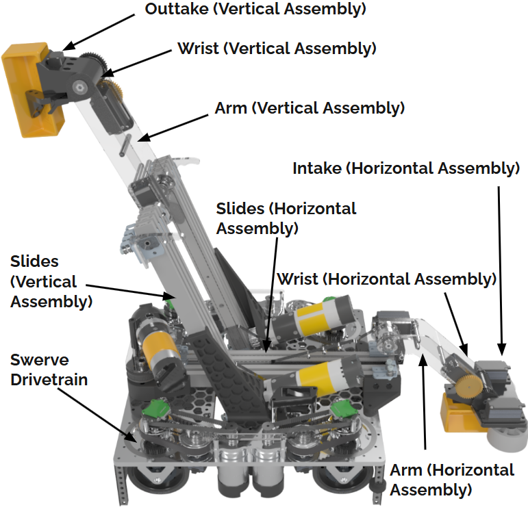
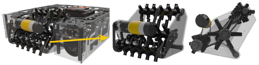
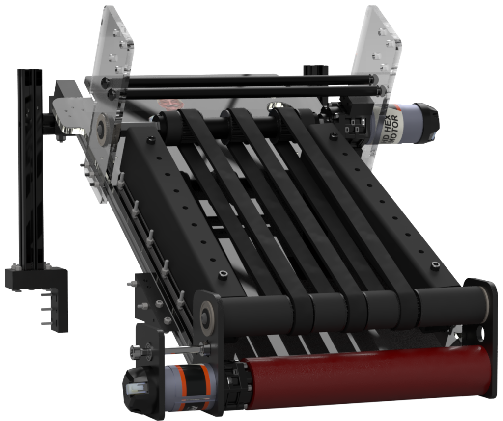
Intake and Horizontal Arm
Our robot features a custom 3D-printed roller intake powered by Axon Minis. The 1:1 gear ratio wrist mechanism relocates the servo for better balance. The polycarbonate arm includes a colour sensor and is just 1/8″ off the floor.
It uses two-stage Misumi slides with a Yellow Jacket motor (3.7:1 ratio) and bevel gears for optimal motor placement, extending up to 22 inches to reach into the submersible.
Vertical Claw
Our gripper claw is powered by a single Axon Micro motor in a 1:1 direct drive setup and driven by 2 custom-printed spur gears for synchronized claw movement. It is also designed to fit samples perfectly and ensure smooth horizontal to vertical transfers. Initially tight-fitting, the gripper was adjusted to allow sliding for optimal alignment, with ridges added for enhanced grip and stability.
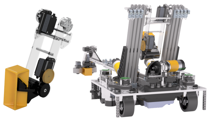
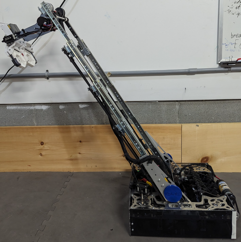
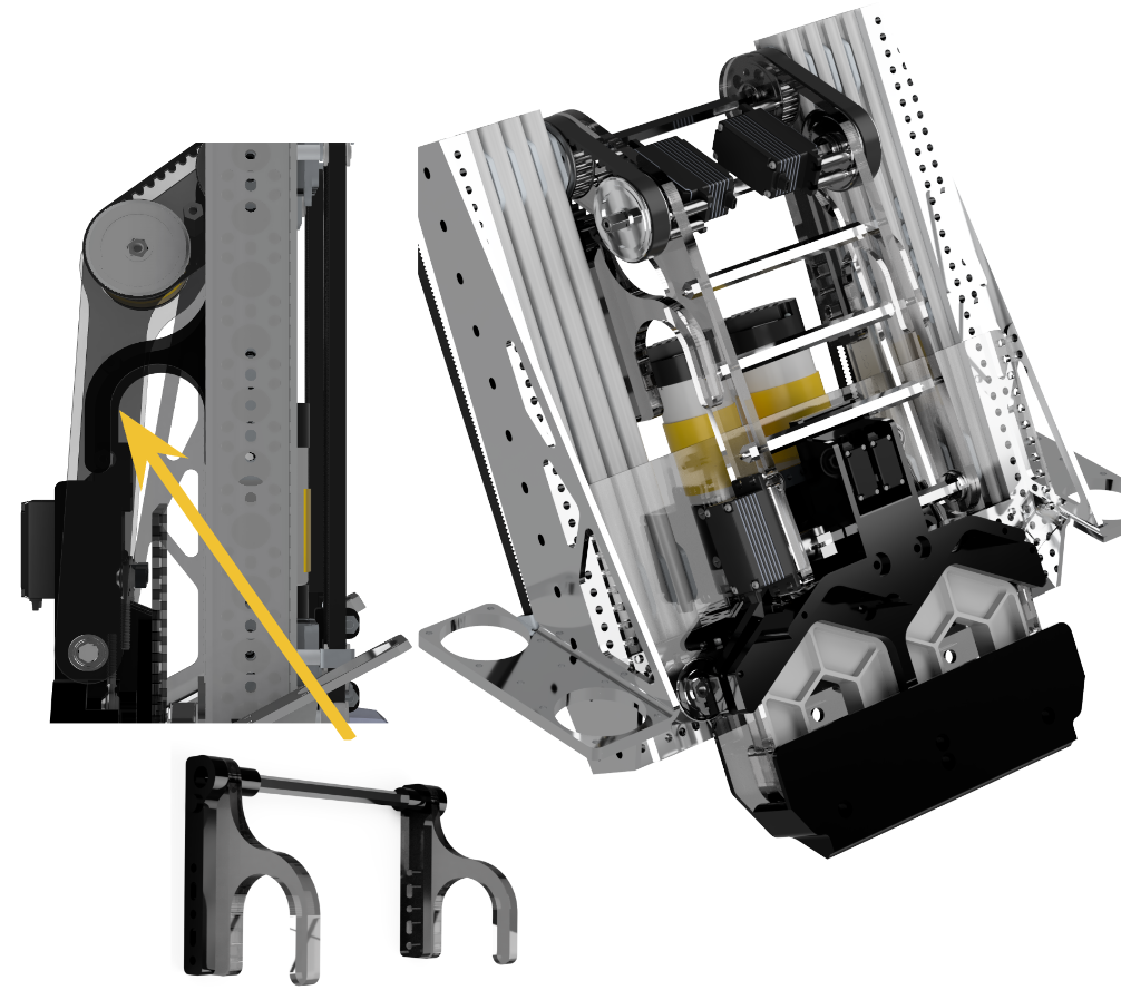
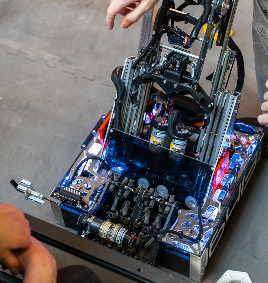
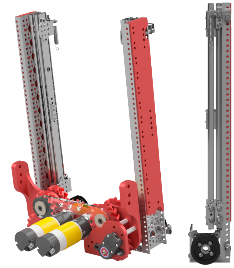
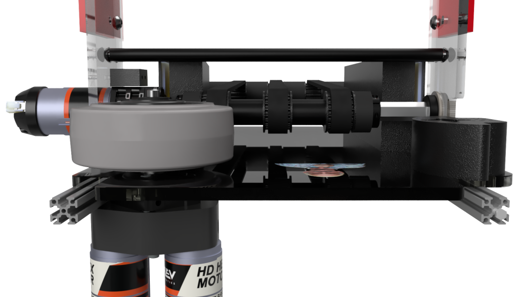
Vertical Slides
Driven by two Yellowjackets (5.2:1) through belts and Misumis, our 4-stage, 20-degree angled custom mount is inset into the drive base for optimal packing and balance. We updated our motor ratio from 13.7:1 to 7.8:1, doubling the cycle speed and enhancing both climbing and cycling efficiency. Initially, the spacing we used between the slides was too close, impacting the effectiveness of the bearing movement. After multiple iterations and size adjustments, we had it tuned perfectly, ensuring the best slide movement.
Climber
Using JVN’s Mechanical Design Calculator, we designed our elevator to lift the robot for climbing, ensuring it could handle the necessary load by testing our battery’s internal resistance. The climber is mounted to the innermost stage at the lowest point. It pulls the bar toward the robot when it retracts, allowing the secondary hooks to latch. After the intermediate latch is secured, the elevator extends again to reach the second bar, completing the climb.
Robot Design
We have 9 different subsystems on the robot.
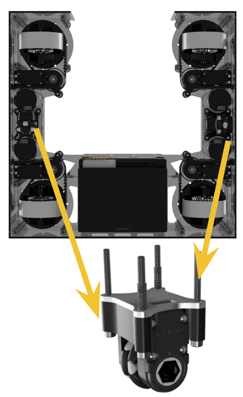
Drivebase
We originally powered our drivetrain with Modern Robotics motors with an external 11.35:1 ratio. However, this drained too much current from our mechanism, so we changed them to a 12:1 external ratio.
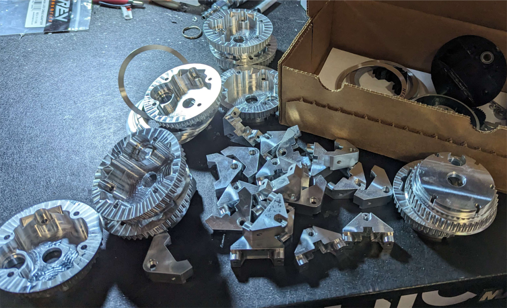
Last year, the robot’s total mass was 32 lbs, but our drivetrain took too much current. To rectify that, we changed to a 12.65:1 ratio, shaving 11 lbs off the robot’s weight to draw 8 amps less current than previously. With the custom billet swerve module, we were also able to make the drivetrain more efficient, reaching a final efficiency of 95% from the motor to the wheel.
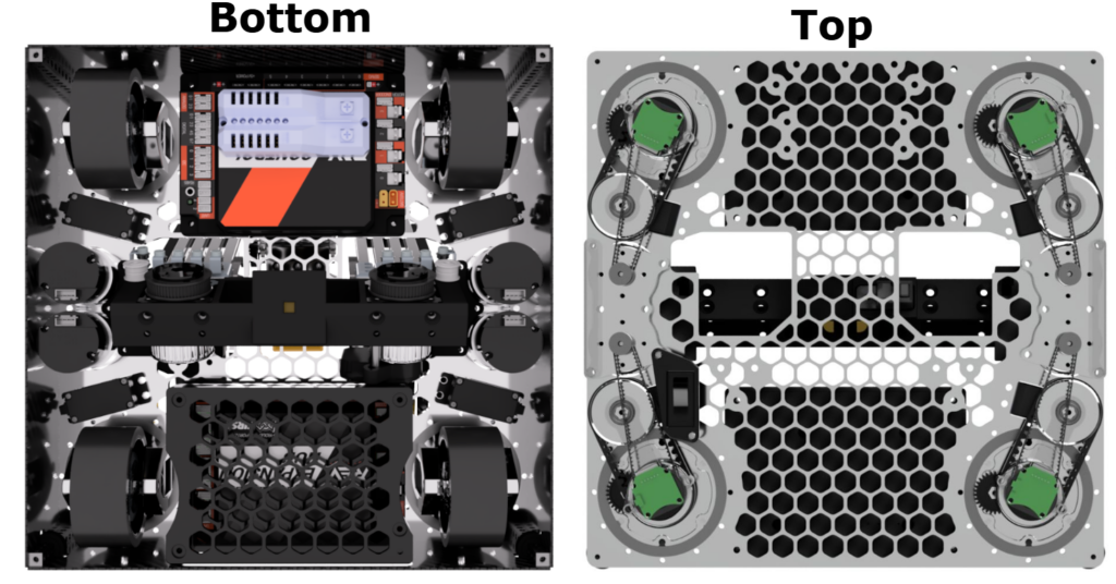
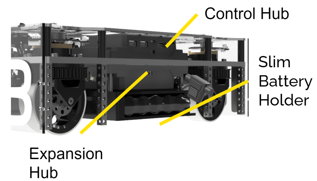
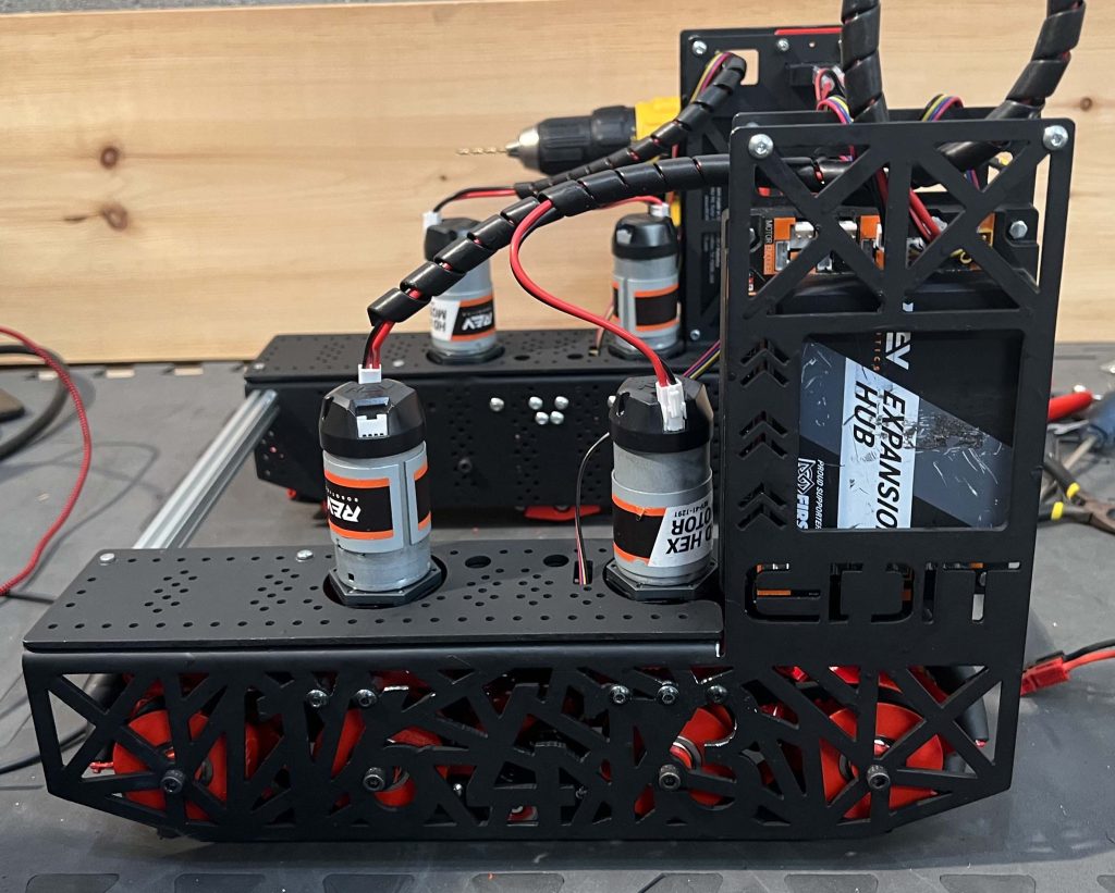
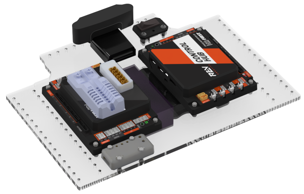
Control Panel
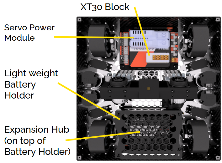
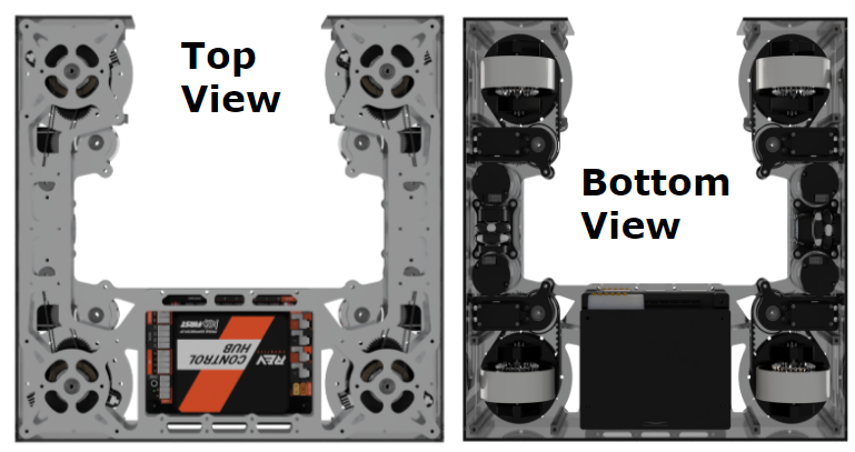
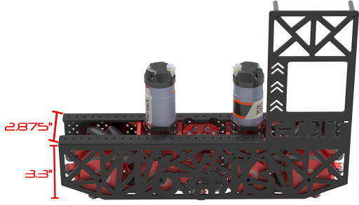
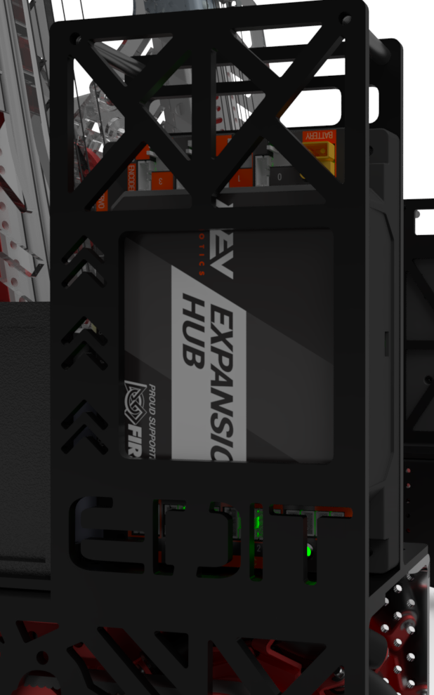
The ¼” drive base panel is cut to fit the Control Hub on the front of the robot and the Expansion Hub on the back, both mounted underneath. Placing the hubs equally on each half of the robot assists in mass distribution. The battery is mounted below the Expansion Hub to lower the robot’s centre of gravity as much as possible to prevent tipping while climbing. Moreover, the specifically selected mounting spot of the battery assists in moving the robot to the correct angle while it climbs to the high bar.
We mounted the XT30 Power Distribution Block and the Servo Power Module underneath the bottom of the robot.
We use the Servo Power Module for the servos that need the most torque (drivetrain + intake wheels) and the 5v Control Hub ports for the lower current applications (arm and wrist).
We have a belly pan underneath our robot to contain the wires on the bottom.
FTC 2024/2023 Season
Mentor of 3D Design, Build & Drive Coach
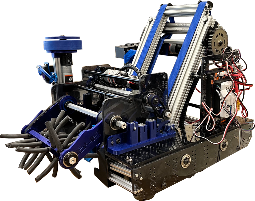
Our robot’s compact design fits within a 14x14x12-inch frame, which is the smallest we could make it for easily moving around other robots. It is constructed from waterjet aluminum plates for maximum strength and minimal size. We transitioned from Modern Robotics motors with a 6:1 ratio to a 12:1 ratio, improving the current efficiency of our mechanisms.
Intake
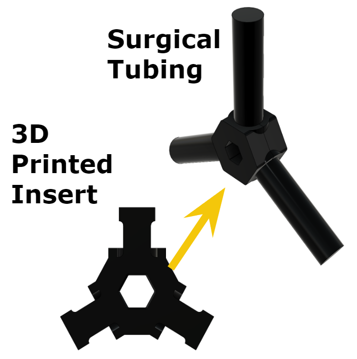
The intake system consists of surgical tubing on rotating axial and goBILDA wheels powered by a goBILDA motor with a belt reduction system. It pulls the game pieces in and kicks them off the ground into our gripper.
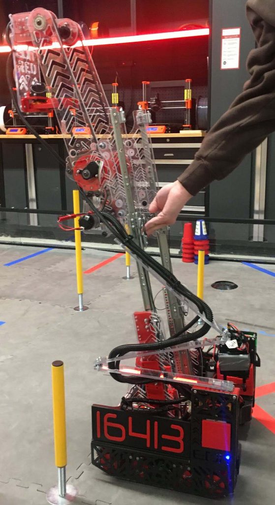
Arm / Elevator / Climber
Our Arm Mechanism is capable of a 250-degree range of motion, seamlessly transporting game pieces from intake to scoring position. Coupled with an Axon Mini+ servo-controlled wrist, the arm features a hard stop for accurate scoring.
We used a 4-stage goBILDA linear slide elevator to surpass the initial scoring line height, enabling quick vertical movement and precise placement of pixels on the scoring backdrop.
The climber utilizes the robust elevator system with polycarbonate hooks to hoist the robot off the ground efficiently, easily meeting the end-game challenge.
Gripper
We designed a dual-sided gripper controlled by two Axon Micro+ servos for optimal control and storage of game pieces, allowing precise placement.
Robot Design
We have 8 different subsystems on the robot.
Drivebase
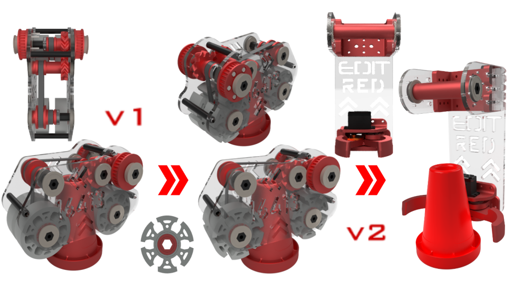
We were the first Canadian team to create a coaxial swerve drivetrain to maximize our robot’s agility and traction, which was critical for the season’s strategic gameplay and required precise placement and robust defence. The sweep drivetrain allows for holonomic movement, meaning the robot can move in any direction without stopping to turn, offering us a competitive edge in maneuvering during matches. The swerve drive uses 4 modules with a wheel on each corner. There are servos for wheel rotation, encoders for orientation feedback, and motors for driving.
Control Panel / Odometry Pods
We use two small omni wheels with REV encoders, called odometry pods, to determine the robot’s position. One wheel measures movement along the y-axis, and the other along the x-axis. The robot’s heading is tracked using the Control Hub’s built-in IMU.
FTC 2023/2022 Season
Team Captain, Lead of 3D Design & Build, Drive Coach
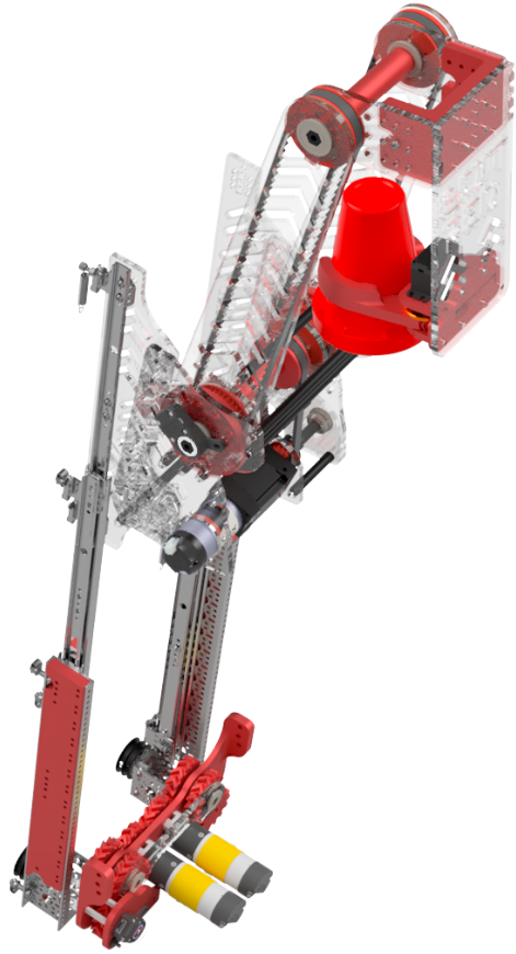
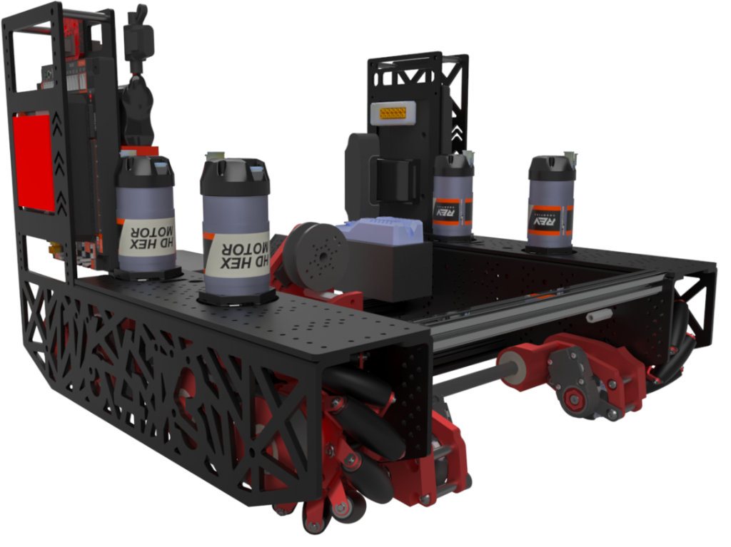
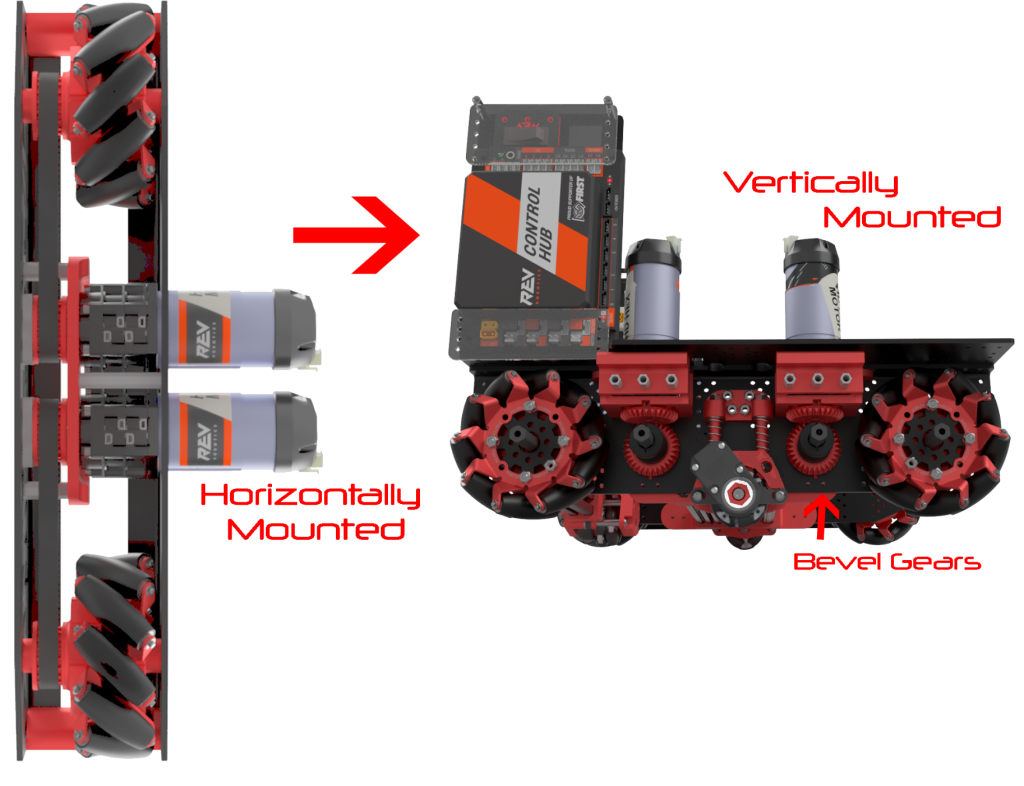
Mecanum Drivebase
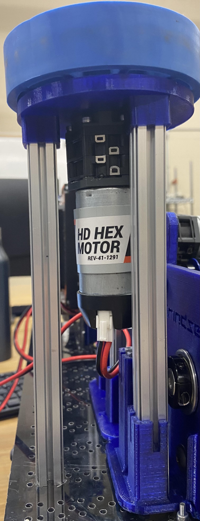
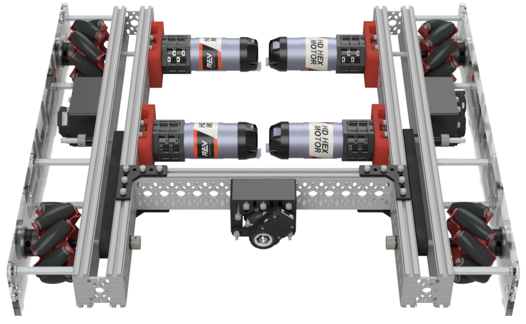
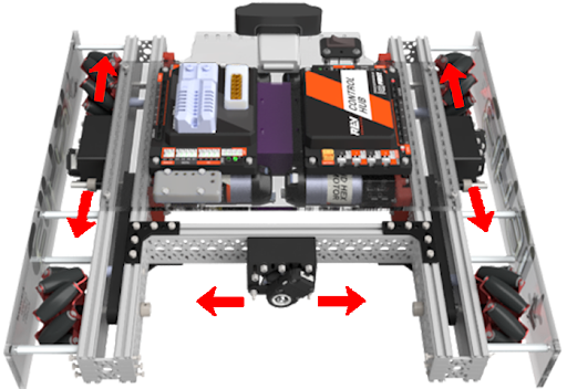
For this year’s game, our team decided to use a mecanum drivetrain as our robot must be capable of holonomic movement because there are very few obstacles on the field to drive over. We switched from 3″ REV mecanum wheels to the 4″ goBILDA wheels to go over the Ground Junction effortlessly. Also, we decided to make the robot as compact as possible, which is 15.5″ by 14″, to move between the Junctions comfortably. The drivetrain’s main structure is made with a waterjet for custom bent and pocketed ⅛” aluminum plates. The drivetrain is powered by 4 REV Ultra Planetary Gearbox HD Hex Motors mounted vertically, making the channels very narrow at a 16:1 gear ratio. Originally, they were mounted horizontally, but it obstructed the intake pass-through. We used a combination of 3D-printed bevel gears and 5mm HTD belts and pulleys to transfer power between the wheels and the motors. We use dead axles fastened between the outer and inner panels to provide more rigidity. Minimal use of fasteners allows for easy removal of the exterior panels and quick drivetrain maintenance.

Control Panel
The top plate of both channels on the drivetrain is bent 90º vertically to hold up the control and expansion hubs. Mounting the hubs vertically gives us extremely easy accessibility to the ports on the control hub. We mount the alliance markers on the front of the hubs and the REV Blinkin LED Driver, the XT30 Power Distribution Block and the Servo Power Module on the back of the hubs. Placing the hubs on separate sides allows us to easily wire all 8 motors as we have 4 on each side of the robot corresponding to the 4 motor slots on each hub.
Arm Mechanism
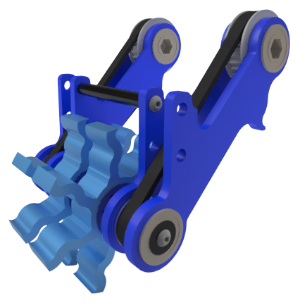
In order to quickly move cones through the robot, we designed an arm that transports the cones from the front, where we pick them up, to the back to score them onto the junctions. Our arm is a Virtual 4-Bar, so the cones stay parallel to the ground as the arm articulates to 140º.
Robot Design
We have 6 different subsystems on the robot.
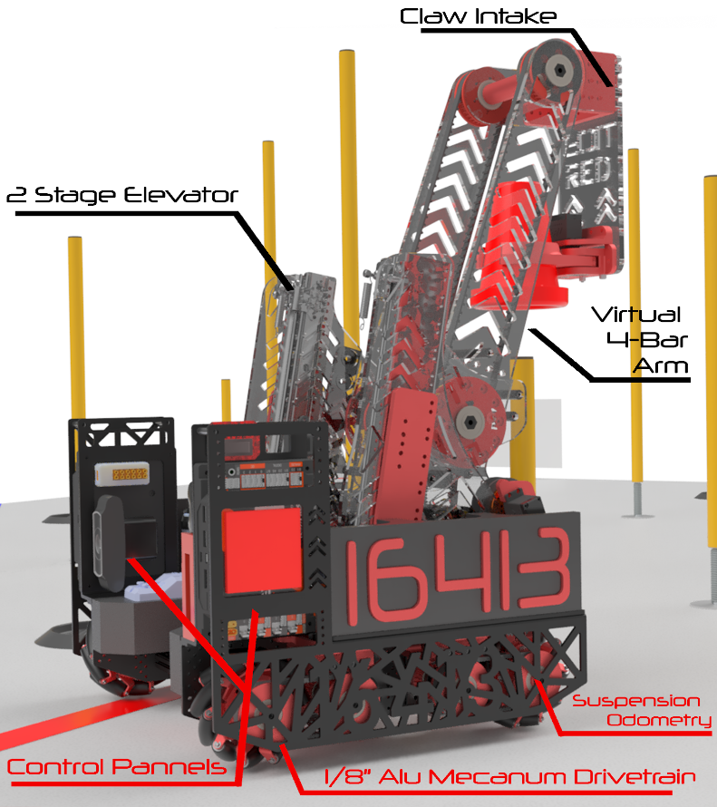
Suspended Odometry Pods
The three odometry pods are vital for knowing our autonomous position. The two parallel odometry pods were originally located in the channels of the drive base. However, the 3D-printed enclosure containing the odometry pods would canter while driving sideways and snap off during competition. We now have the odometry pods mounted on an aluminum axle at the rear, allowing them to be significantly more rigid.
The parallel odometry pods are suspended with a single wishbone design fabricated out of steel, which allows them to spin with the ground consistently. The lateral odometry pod is hung by a string tied to a pulley on a servo in the center of the robot. This allows us to retract the odometry pod when it is no longer needed in TeleOp.
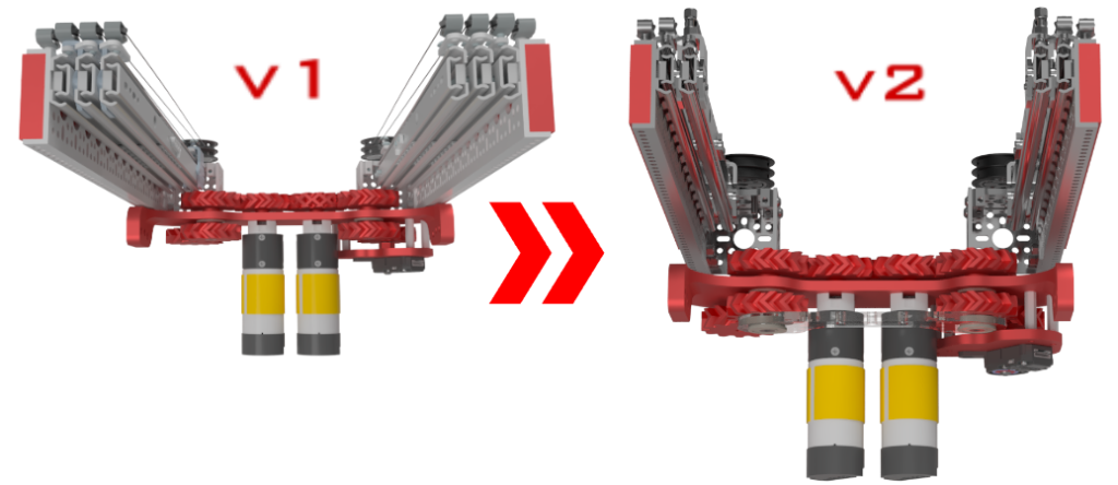
Intake
We could originally intake cones by deploying the intake from above the cones and dropping it onto them, which gave us room for error. It pressed the cone between the two 30A durometer 3” flex wheels and pulled the cones upwards. We changed our intake by cutting the flex wheels in the shape of a “sun” design to have a firmer grip on the cone. However, at our first competition, we found this design inefficient, as it was too heavy, and we had to raise and lower the arm every time we wanted to intake a cone. We switched to a claw, which grabs cones from the side using two 3D-printed parts. This is powered by a servo motor, which turns one part directly and one through a herringbone gear. This approach also allows us to intake cones from the Starter Stack in Autonomous.
Linear Slide Elevator
Even though we already had an arm that could place the cones at the low Junction, the arm required to be higher up for the medium and high Junctions. This resulted in us mounting the intake and arm on two 2-stage goBILDA linear viper slides. The elevator is powered by two goBILDA yellow Jacket Planetary Gear Motor at a 13.7:1 Ratio for 435 RPM and can fully extend in 1.2 seconds. To easily program the elevator, we mechanically linked the motors with an external encoder, making the slides spin in opposing directions in a gearbox of 8 custom 3D printed herringbone gears, as the helical pattern of this gear gives us the advantage of more torque. Originally, the string was not strong enough to pull up the intake and arm mechanism, so we used a thicker braided kevlar fibre string that has a strength of 400 lb.
Since our arm’s length increased after switching to a claw design, we removed a stage from the elevator to reduce weight.
As our intake goes outside of the robot perimeter, we added 2 counterweights that also act as a funnel for the cones, equal to the weight of the intake (10lb) made of steel and cut on a horizontal bandsaw. We mounted them on our drivetrain to ensure our robot could not tip.
FTC 2022/2021 Season
Team Captain, Lead of 3D Design & Build, Drive Coach
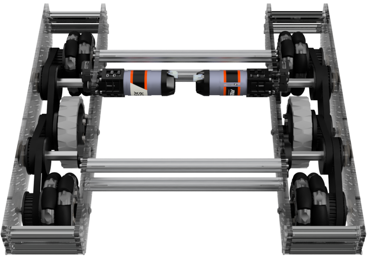
DriveBase
We chose a combination of 2 omni wheels and a traction wheel on either side to effortlessly surmount obstacles on the field. We attached the motors to custom Lexan side plates, and each of the slide plates is held together by a 15mm Extrusion.
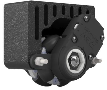
Only 1 REV Ultra Planetary Gearbox HD Hex Motor at a 20:1 gear ratio powers each side of the drive base. We use a system of 3D-printed pulleys and 5mm pitch HTD Timing belts to transfer power between each wheel.
Carousel Spinner Mechanism
The carousel is spun by one flex wheel. We chose the flex wheel as it could compress against the carousel, which adds stability while spinning it.
Deployable Intake
Our intake uses two mechanically linked Rev Ultra Planetary motors in a VersaDM gearbox at a 15:1 gear ratio. To transmit power from the motors to the deployable front intake, we use two custom 3D printed herringbone gears, as the helical pattern of this gear gives us the advantage of more torque.
Our intake is deployable to fit within the 18” size restriction. Custom CNC Lexan side plates and aluminum standoffs hold together the intake. Power is transmitted from the font intake to the inner intake with several pulleys and belts. The front automatically drops down when the motor is started, using thick surgical tubing to compensate for the inner intake lack of range.
Inner Intake
The inner intake is designed to pick up both spherical and cubic freight. It is comprised of two custom 3D-printed TPU (Thermoplastic Polyurethane) flex wheels in the shape of a “sun” design. The sun design gives us the advantage of being able to grab the corners of the cubes and the ducks. Due to its flexible material, it compresses against the spherical freight.

Robot Design
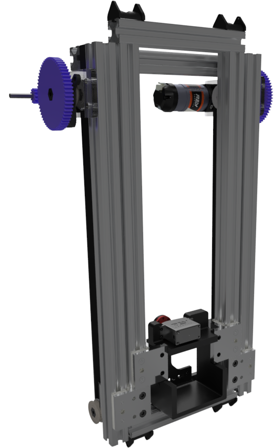
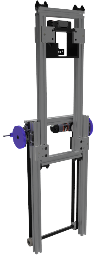
Elevator / Outtake
Our outtake is a two-stage elevator. The first stage is the inner two extrusions, and the second stage is the horizontal extrusion.
Motors connected to the two black belts rotate them, which slides the first stage up.
The dual blue belts connect the second stage to the first. As the first stage rises, it drags the second stage with it, sliding along the first stage extrusions.
The parallel odometry pods are suspended with a single wishbone design fabricated out of steel, which allows them to spin with the ground consistently. The lateral odometry pod is hung by a string tied to a pulley on a servo in the center of the robot. This allows us to retract the odometry pod when it is no longer needed in TeleOp.
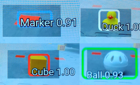
Object Detection with Camera
We have used the built-in Tensorflow object detection (tfod) with Vuforia and an external C920 Logitech Camera to confidently detect the position and existence of the game elements, which we use during the Autonomous period. Furthermore, have a custom EasyOpenCV pipeline for duck and team shipping element detection. We detect ducks by converting the image from the camera to YCbCr colour space so that our detection isn’t impacted by the level of lighting in the room. Next, we detect the average value of the Cb channel in each possible barcode position. We assume the average location with the darkest value in the Cb channel to be the duck since the duck is bright yellow, the opposite of blue.
FTC 2021/2020 Season
Lead of Programmer, 3D Design, Build & Robot Driver
DriveBase
For this year’s game, our team decided to use a mecanum drivetrain as our robot must be capable of holonomic movement because there are very few obstacles on the field to drive over. We switched from 3″ REV mecanum wheels to the 4″ goBILDA wheels to go over the Ground Junction effortlessly. Also, we decided to make the robot as compact as possible, which is 15.5″ by 14″, to move between the Junctions comfortably. The drivetrain’s main structure is made with a waterjet for custom bent and pocketed ⅛” aluminum plates. The drivetrain is powered by 4 REV Ultra Planetary Gearbox HD Hex Motors mounted vertically, making the channels very narrow at a 16:1 gear ratio. Originally, they were mounted horizontally, but it obstructed the intake pass-through. We used a combination of 3D-printed bevel gears and 5mm HTD belts and pulleys to transfer power between the wheels and the motors. We use dead axles fastened between the outer and inner panels to provide more rigidity. Minimal use of fasteners allows for easy removal of the exterior panels and quick drivetrain maintenance.
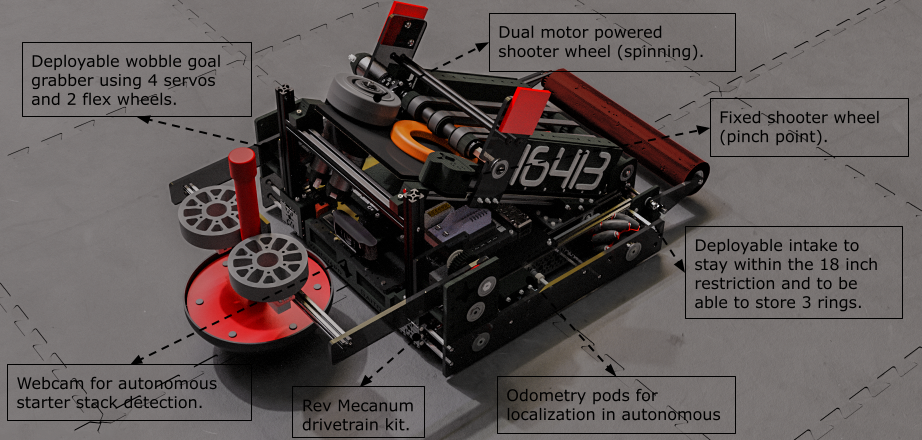
Odometry Pods
The Odometry pods are vital for knowing the position of the robot in both autonomous and teleop. There are three pods placed on the robot. The custom side plates on the drivetrain have been made with enough room to accommodate the two parallel odometry pods on either side and one perpendicular pod that sits in the middle, between both side channels.
Each odometry pod consists of an omni wheel and a REV Bore Through Encoder with a custom 3D printed mounting enclosure.
Intake
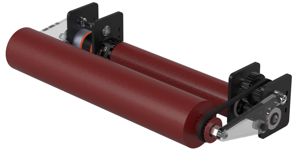
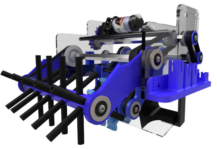
We can take the rings off the field using two rollers. The rollers are two ABS pipes coated in Plasti dip to grip the rings better. We use a direct-driven Rev HD Hex Motor that powers the bottom roller. The bottom roller is belted to the front roller, making the two rollers spin towards each other. The front roller compresses the rings against the mat, pushing the rings toward the bottom roller, which then lifts the rings off the ground. Our intake is deployable to fit within the 18” size restriction.
Index
To transport the rings from the intake to the shooter, we thought it vital for our robot to be able to store three rings using a 140-tooth HTD Timing Belt Feed Conveyor. The index compresses the ring against the bottom roller and the top index belts. Then, the index belts convey the rings up the custom CNC’d Lexan plate to the shooter mechanism.
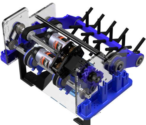
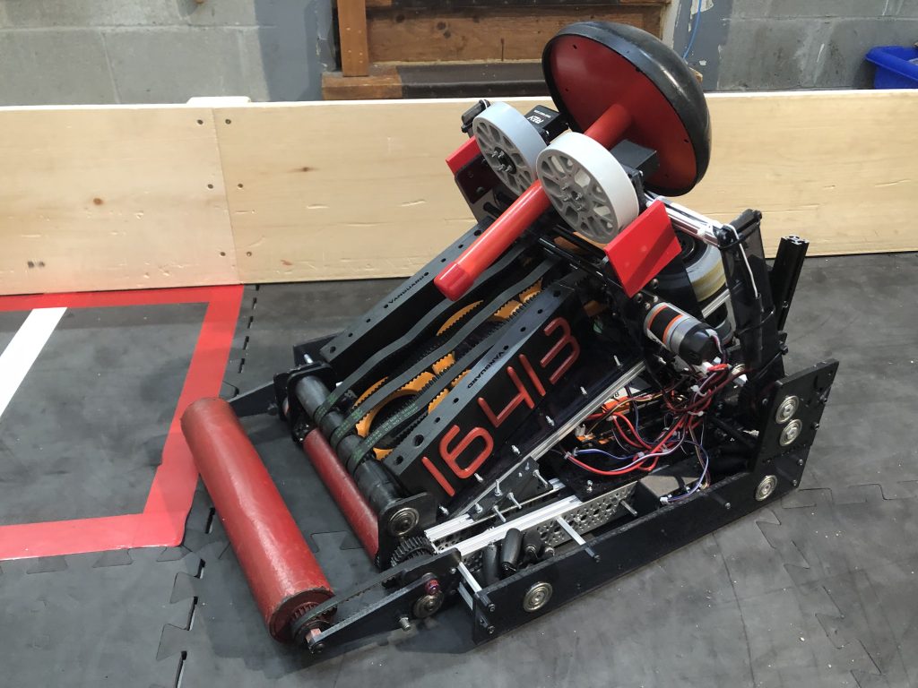
Shooter
In order to score rings, our team decided that we needed a shooter mechanism that could shoot rings precisely in the high goal and power shots. We found that the best way to shoot straight with power would be to compress the ring against a high-speed wheel and 3D-printed fixed wheel as a pinch point. This system uses two mechanically linked REV HD Hex motors at 1:1 gear ratio attached to a heavy 4” Colson inertia wheel. When powering both wheels, we found that the rings floated rather than spun in mid-air. After prototyping, we found that half an inch of compression works best for our shooter. When we tried an inch of compression, it over-compressed the rings, causing poor deceleration.
We needed to have the two linked motors shooting at 6000 RPM for our team’s shooter mechanism. We used a PID error correction to ensure consistent angular velocity while shooting. A PIDF loop takes the error and proportionally applies power to reach the RPM setpoint. After adjusting the PIDF constants, we saw dramatic improvements in consistency and accuracy. The derivative of the error (to reach the setpoint quicker) and a feedforward constant to account for any static friction in the system.
Wobble goal
To intake and lift the wobble goal, we decided on making it deployable to fit within the 18” size restriction. It uses 4 servos and two flex wheels. 2 servos for articulation to lift the wobble goal with additional with 36:26 gear reduction and 2 continuous rotation servos and 4” flex wheels to intake the wobble goal. Assembled with CNC’d ¼” Lexan mounting Plates, 3D Printed gears and a 15mm aluminum extrusion

Robot Design
We have 7 different subsystems on the robot.
To perform complex autonomous movement trajectories and track real-time robot motion, we implemented a system of odometry, path planning, and path following using the Road Runner library. To perform robot localization, we collect rotation data from REV encoders attached to unactuated omni wheels and transform that data into our robot’s position.
Control Panel
The control panel holds all of the electronics on one Lexan plate.
Computer Vision Processing
We use our C920 Logitech Camera with a custom vision pipeline based on the FTCLib + OpenCV Library for Java to perform autonomous starter stack height classification. During image processing, our pipeline applies a blur filter to smooth any curves and blend the stack together to render further processing easier. Next, we search for pixels in the image that meet a certain threshold of “orange-ness” of a pixel. After we search for the largest continuous contour to detect where the rings are, we can finally calculate the starter stack’s size by the contour height ratio to the camera’s resolution. This method can confidently predict the number of rings in the stack.