4 Month (Sept. 2024 – Dec. 2024)
MIE243 – Mechanical Engineering Design
Final Project – Hobbyist CNC Design
Candidate Designs
Candidate 1: 3-axis Full Belt driven
- Pros – Major and Minor considerations
- Low price point relative to lower tolerance or higher degree of freedom models
- Minimal number of components to be manufactured in-house
- More readily available components (belts)
- It is cheaper to replace components that are most likely to break (belts)
- Cons – Major and Minor considerations
- Relatively low accuracy in the X-axis compared to other candidates
- Prone to belt skipping under load
- Requires a designed point of failure to prevent skipping
- Requires a tension screw
Candidate 2: 3-axis leadscrew X driven
- Pros – Major and Minor considerations
- Relatively high accuracy in the X-axis when compared to other candidates
- No belt skipping (in the X-axis)
- No tensioning is required (in the X-axis)
- Cons – Major and Minor considerations
- More costly
- Less readily available components (7-foot lead screw)
- More custom components are required
Candidate 3: 3-axis ballscrew Z driven
- Pros – Major and Minor considerations
- Lowest available Z axis tolerance
- Cons – Major and Minor consideration
- Very expensive for minor improvements in Z tolerance
- No further benefits in relation to design 1
Candidate 4: 4-axis zenith rotation
- Pros – Major and Minor considerations
- Flexibility in manufacturing space
- Milling on cylindrical surfaces
- Cons – Major and Minor consideration
- Highest number of custom parts
- Increased cost relative to belt-driven 3 axes for limited increase in manufacturing space


Dissection Drawings
Dissection 1 – Drafting, Ball Bearing Hand drafting
Dissection 2 – Jigsaw
Dissection 3 – Can Opener
Dissection 4 – CAD, Screwdriver
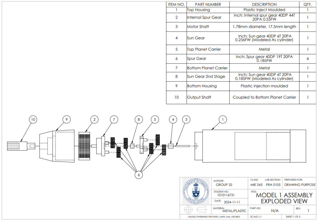
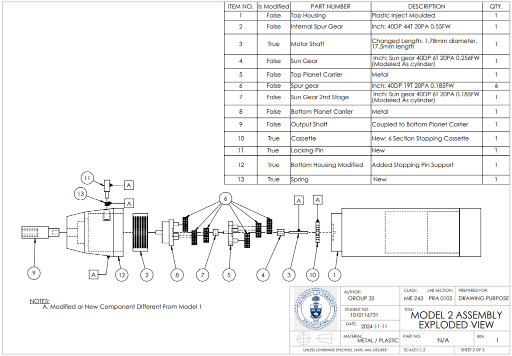
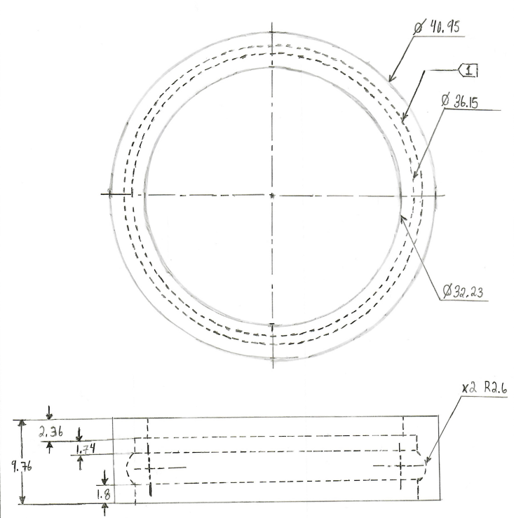
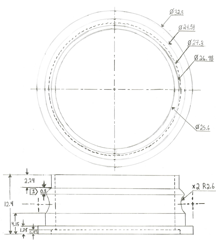
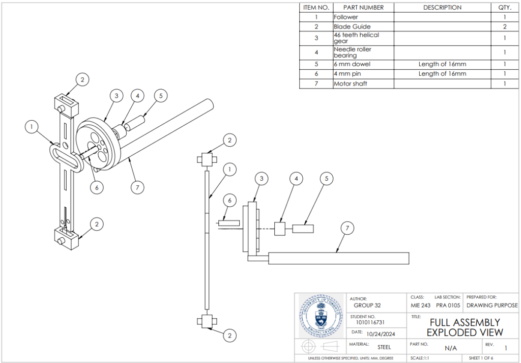
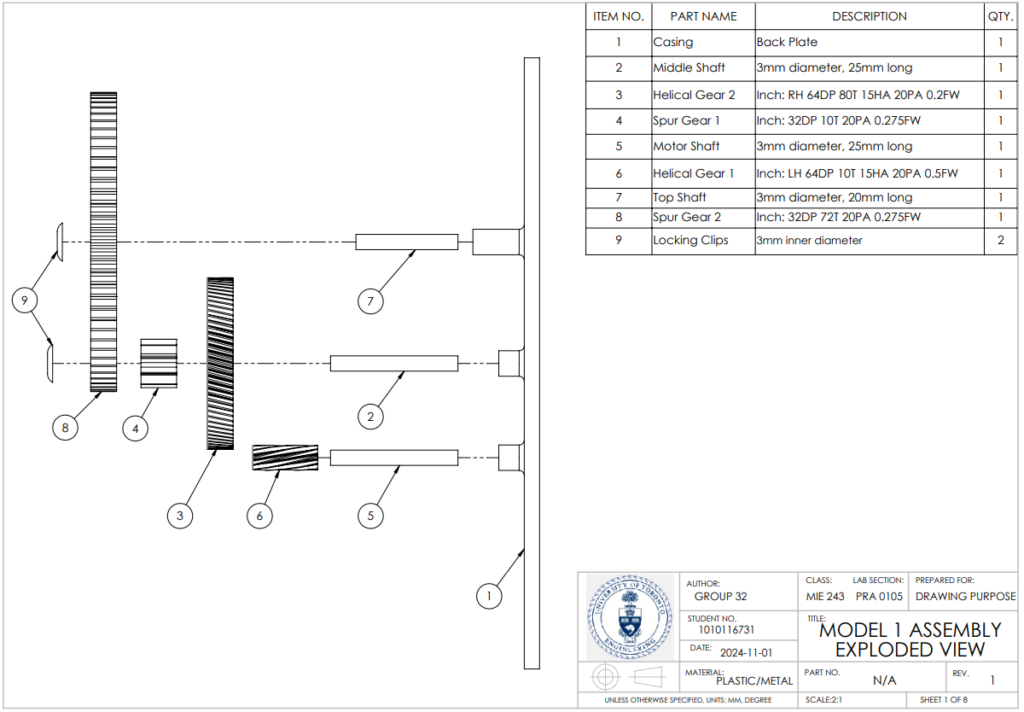
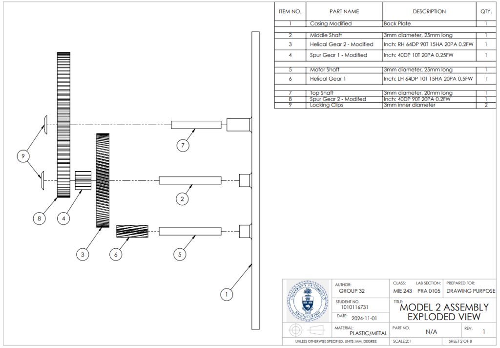
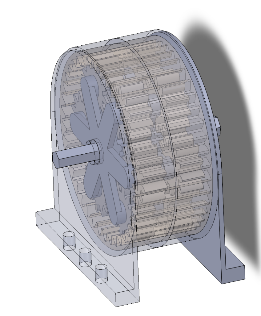
Dissection 5 – CAD and CAM, Gearbox Design

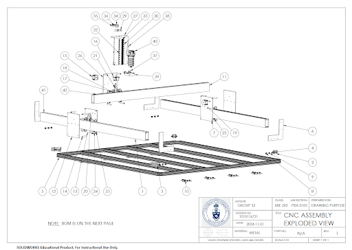
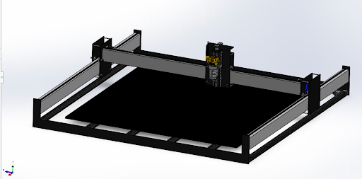
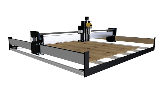
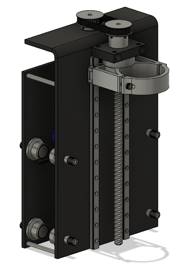
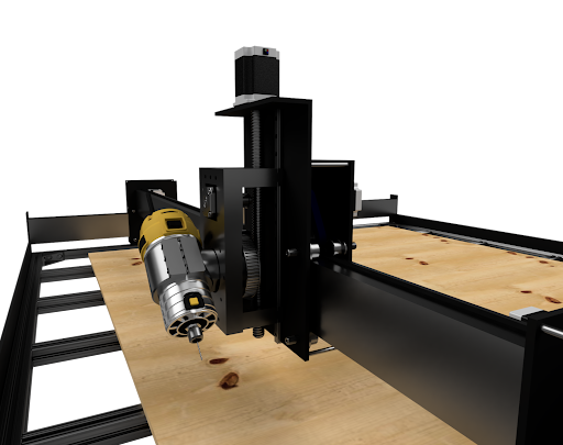
After evaluating the candidate designs, Candidate 1 was chosen for its low cost, minimal custom components, and simple functionality, making it ideal for a hobbyist CNC machine. The final design uses square tube aluminum framing for a spacious 5 ft x 5 ft working area and employs a belt-driven system for the X and Y axes. This cost-effective power transmission method avoids the high cost of machined racks and reduces alignment issues.
To control costs, rolling bearings in the X and Z-axis carriers were replaced with affordable copper bushings, which slightly increased friction but significantly reduced expenses. The spindle mount, attached to the X-axis carrier, uses a belt-driven lead screw powered by a smaller NEMA-17 motor to cut costs further. An 80mm spindle mount, sourced from Amazon, accommodates the 2.2 kW spindle needed for cutting aluminum.
4 Months (Jan. 2024 – Apr. 2024)
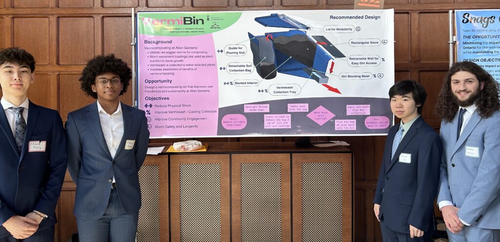
Praxis II – Vermi Bin Allen Garden
Opportunity
The project presents an opportunity to revamp the vermicomposting system at Allan Gardens, focusing on reducing physical strain for workers, streamlining the casting collection process, and enhancing worm safety and longevity within the composting ecosystem.
Background
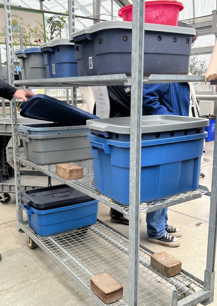
Vermicomposting at Allan Gardens uses red wiggler worms to break down organic material. The resulting castings enrich plant soil, while vermiwash, the nutrient-rich byproduct, waters and nourishes plants.

My Role
I was responsible for sourcing the materials and conducting CAD modelling of various potential solutions, which ultimately helped us converge on the final design. I took the lead in the CAD modelling and manufacturing of the bin, 3D printing brackets, and blocks to secure the custom-cut Lexan plate in place. Additionally, I contributed to the visual aspects of our project by assisting with designing the poster and handout materials.
Current Design:
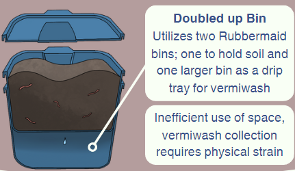
Recommended Design: Vermi Bin
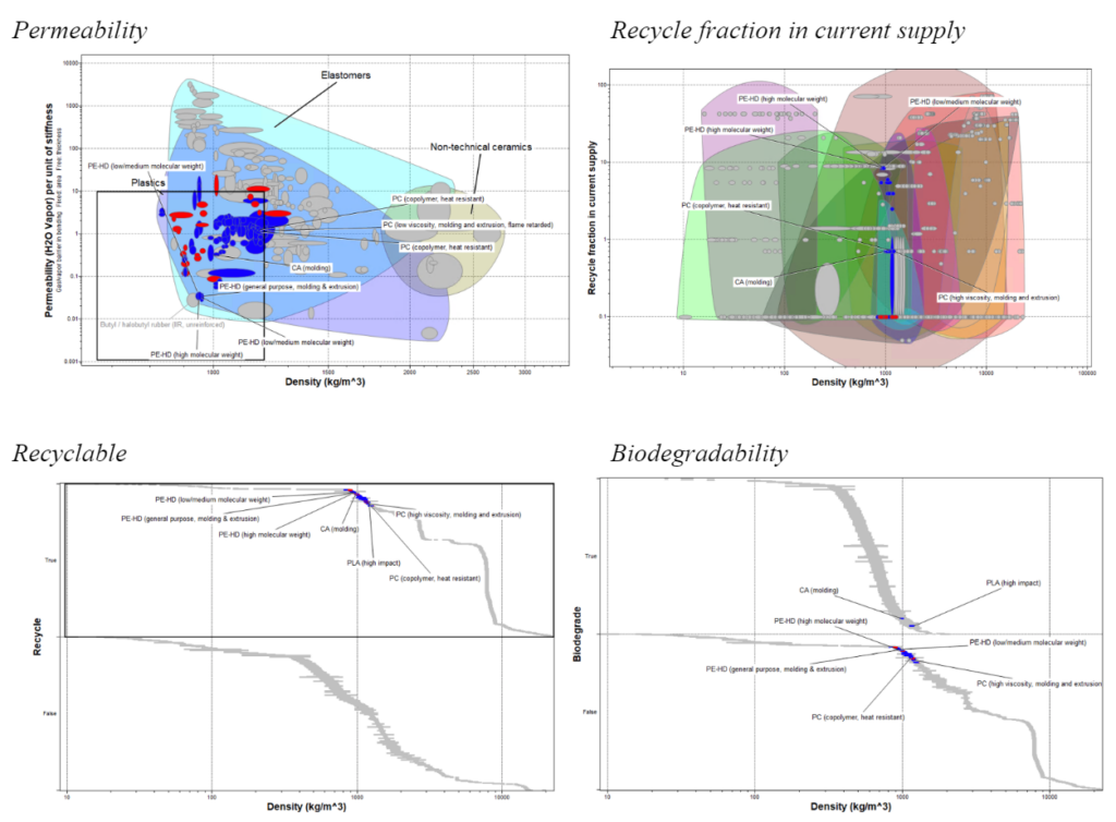
Material Selection
PE-HD (high-density polyethylene)
- Low water permeability
- Recyclable (Recycling rate of ~10%)
- Not biodegradable
- The material used in the current design
- Does not need new material produced

The Design
Allan Gardens emphasized simple designs for their vermicomposting bins. Workers preferred fewer parts to avoid inconvenience. The design was also developed with sustainability in mind, modifying existing bins rather than replacing them to adhere to the UN’s Sustainable Development Goal of Responsible Consumption and Production. The use of High-Density Polyethylene (HDPE) ensures durability and recyclability.
- Retractable Wall: Facilitates easy access to soil and casting collection.
- Rectangular Sieve: Separates castings efficiently with minimal disturbance to worms.
- Slanted Interior: Directs vermiwash to a new collection tray, eliminating the need for a second bin and streamlining the harvesting process.
- Handle Placement: Positioned to align with the center of mass, reducing the torque required during transportation.
- Dirt Collection Bag: Offers convenient interim soil storage, improving the collection workflow.
Evaluation
- Dirt Return Mechanism: Simplifies the soil return process post-harvest.
- The VermiBin design is 18% more ergonomic than the current system, as evaluated against ISO 11228-1 standards.
- Water efficiency is significantly improved, with 98% of introduced water being properly drained, a 58% increase in effectiveness over the existing system.
- The VermiBin maintains the 38L capacity of the current bins, ensuring user volume consistency.
4 Months (Sept. 2023 – Dec. 2023)
CIV102 Matboard Bridge
Opportunity
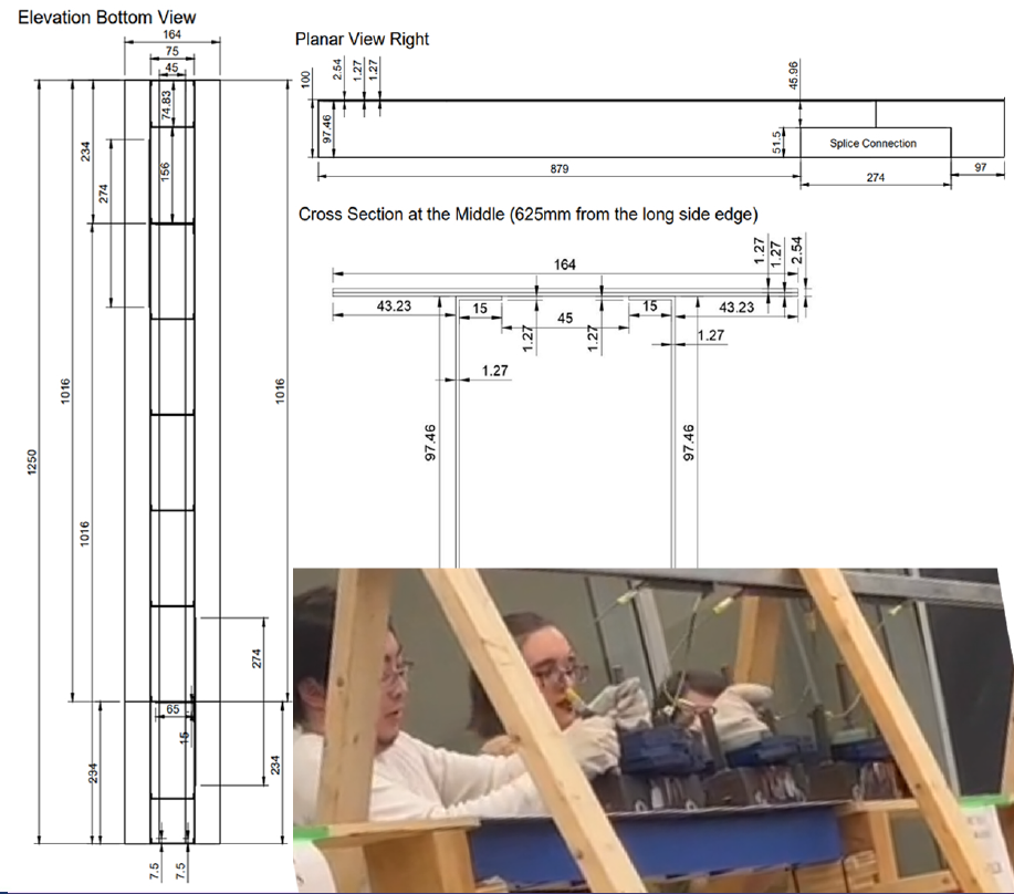
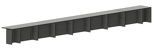
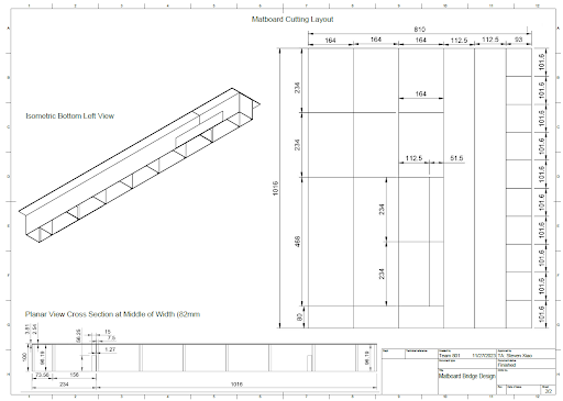
In the CIV102 Matboard Bridge Design Project, our team’s goal was to create a bridge capable of supporting the most load possible given only one sheet of matboard. After rigorous programming by Edward Liu and Tae-Kyeong Kim, we settled on a final design optimized from a basic beam bridge concept. Our bridge spanned 1250mm, with a cross-section featuring two 164mm x 1.27mm rectangles as the top flange and two 97.46mm vertical webs, ensuring both strength and efficiency.
My Role
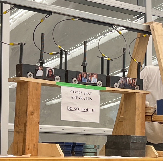
As the lead bridge builder, I focused on translating our theoretical design into a robust physical model, applying precision in craftsmanship to achieve the load-bearing goal.
I used CAD to meticulously plan our material layout meticulously, ensuring optimal use of matboard and minimal waste. Then, I 3D-modelled the bridge to ensure the assembly would work.
I strategically scored along the bending lines to facilitate clean folds. This technique was essential for preparing the diaphragms and glue tabs, allowing us to shape the matboard with precision and reinforce the structure’s stability with well-placed adhesive.
I started by securely bending the top flange pieces, using tape to hold them in place as the glue set. With the same attention to detail, I ensured the diaphragms and glue tabs were correctly aligned and fixed at right angles. I reinforced the bridge’s integrity with tape to maintain the alignment until the glue cured. I diligently filled any small gaps between the pieces with surplus glue to eliminate any areas of weakness.
Design
Key design decisions prioritized minimizing material while maximizing load support. We chose a dual-webbed structure to distribute flexural and shear stresses evenly. After exploring various shapes and cross-sections, including trapezoidal and varying web designs, we identified that a uniform two-web design most effectively met our requirements.
Our construction process involved precision planning and strategic assembly. This design was chosen for its strong theoretical load capacity, construction practicality, and materials’ optimal use. While alternative designs offered different benefits, the final design struck the best balance between these key considerations. Our bridge withstood a load of 770N, placing us in our cohort’s top 10 out of 92. Also, we received a high grade for the quality of the build.
4 Months (Sept. 2023 – Dec. 2023)
Praxis I – Reduce Wasting Water in Water Bottle Refill Stations
Opportunity
In the Praxis I project, our team tackled the opportunity of reducing wasting water in water bottle refill stations at Myhal during the refilling process.

My Role
On the team, my role was multifaceted, encompassing electrical engineering, programming, and leadership in the design of our prototypes. I was responsible for creating and developing CAD models and initial prototypes for three of our five design concepts. After we did proxy testing, I completed the assembly, programming, and electrical setup of the chosen design. Beyond these technical contributions, I helped with the visual and informational aspects of our project by enhancing our presentation slides, and I created the one-pager and flowchart that clearly outlined the operational control flow of our design. I guided teammates on how to use the technology but also understand it, fostering a collaborative environment where knowledge was shared and every member felt confident in our design.
The Design
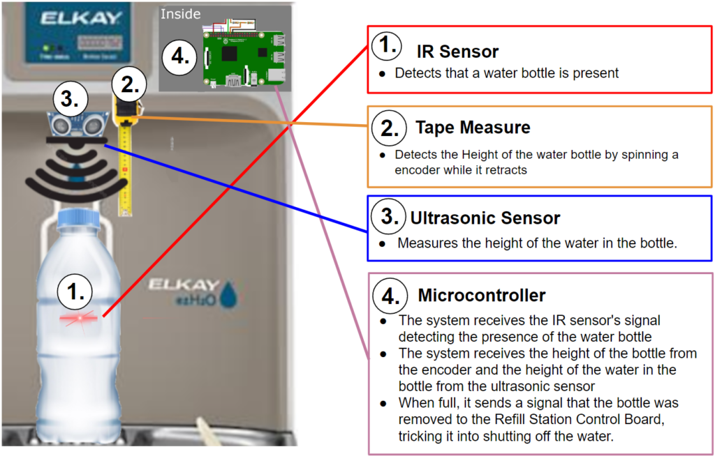
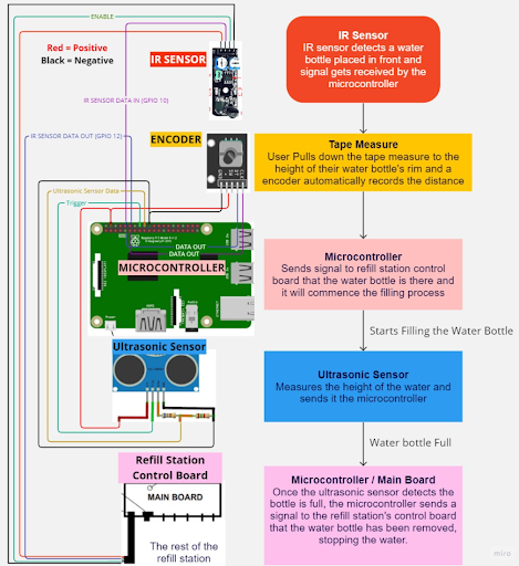
Our team’s design involved an ultrasonic sensor mounted above the water bottle to measure the distance of the water from the top rim, while a user-operated measuring tape with an integrated encoder identified the height of the bottle’s top. The system was designed to minimize the amount of water wasted, accommodate a range of bottle dimensions, and ensure the fill level was precise and user-friendly.
The IR sensor detects the presence of a water bottle, which activates the system. We used the station’s existing IR sensor for seamless integration and chose durable, low-maintenance components for reliability. As the bottle fills, the ultrasonic sensor ensures the water level is monitored closely with its precise distance measurements. The tape measure, when extended and retracted, feeds back the bottle height data from the encoder that counts its rotations. These components work together and are controlled by a microcontroller that effectively manages the flow in real time, halting it at the perfect moment to prevent overflow and conserve water.